Pipe position locking mechanical valve

A technology for mechanical valves and pipelines, which is applied in the field of position-locking mechanical valves for pipelines, which can solve problems such as hidden dangers of tripping accidents, and achieve the effects of high rotation positioning accuracy, uniform force, and improved service life

Inactive Publication Date: 2017-09-12
JIANGSU SUNDIDE INTELLIGENT TECH CO LTD
View PDF4 Cites 0 Cited by
  • Summary
  • Abstract
  • Description
  • Claims
  • Application Information

AI Technical Summary

Problems solved by technology

For important water supply equipment, the impact is significant, and in severe cases, it will cause potential accidents such as tripping

Method used


Image

  • Pipe position locking mechanical valve
  • Pipe position locking mechanical valve

Examples


Embodiment Construction

[0017] The following will clearly and completely describe the technical solutions in the embodiments of the present invention with reference to the accompanying drawings in the embodiments of the present invention. Obviously, the described embodiments are only some of the embodiments of the present invention, not all of them. Based on the embodiments of the present invention, all other embodiments obtained by persons of ordinary skill in the art without making creative efforts belong to the protection scope of the present invention.

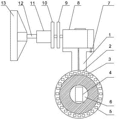
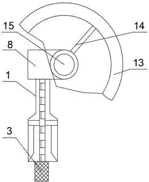
[0018] see Figure 1-2 , the present invention provides a technical solution: the present invention provides a position-locking mechanical valve for pipelines, including a valve body neck 1-valve body 5-disc 6 and a hand wheel 13, and a fixed pipe is connected to the right side of the hand wheel 13 sleeve 11, and the handwheel 13 is connected with the fixed pipe sleeve 11 through the handwheel shaft 12, the right side of the fixed pipe sleeve 11 ...


PUM


Abstract

The invention discloses a pipe position locking mechanical valve. The pipe position locking mechanical valve comprises a valve body neck part, a valve body, a valve part and a hand wheel; the right side of the hand wheel is connected with a fixed pipe sleeve; the hand wheel is connected with the fixed pipe sleeve through a hand wheel shaft; a movable disc is mounted on the right side of the fixed pipe sleeve; the right side of the movable disc is connected with a fixed disc; a fixed ring is arranged on the right side of the fixed disc; a flange is mounted on the lower side of the fixed ring; the valve body neck part is arranged below the flange; the valve body is connected below the valve body neck part; a valve ring is embedded in the valve body, and is provided with a plug column; the valve part is embedded in the valve ring; a valve element is mounted in the valve part; the inner side of the hand wheel is connected with a hand wheel support rod; and the tail end of the hand wheel support rod is connected with a hand wheel rotating core. The movable disc is higher than the fixed pipe sleeve; the flange and the valve body neck part are connected integrally; the movable disc and the fixed disc are produced by stainless steel metal; and the hand wheel support rod and the hand wheel are fixedly connected. The pipe position locking mechanical valve has the following advantages: the improved valve body is low in production cost, convenient in production, high in rotary positioning precision and the like.

Description

technical field [0001] The invention relates to a mechanical pipeline valve, in particular to a position-locking mechanical valve for pipelines. Background technique [0002] The valve has the advantages of small fluid resistance, compact structure, reliable sealing, convenient operation and simple maintenance, so it is widely used in petroleum, chemical industry, power generation, aviation and plumbing, etc. Conventional butterfly valve has simple structure, small size, light weight and small installation size , The driving torque is small, the operation is simple and fast, although the performance stability is not as good as that of ball valves and gate valves, but the cost is low and the cost performance is high, so it is widely used; [0003] At present, the working principle of the butterfly valve is to rely on the valve core to rotate 90° to realize the opening and closing of the flow channel, while the valve core is always affected by the force of the water flow. Dur...

Claims


Application Information

Patent Timeline
Patent Type & Authority Applications(China)
IPC IPC(8): F16K35/00F16K31/60
CPCF16K35/00F16K31/602
Inventor 郑组青郑雪梅徐世斌
Owner JIANGSU SUNDIDE INTELLIGENT TECH CO LTD
Why Eureka
Try Eureka