A Method of In-Situ Measuring Circular Plane Shape Error

A technology of plane shape and circular ring, applied in the field of on-site measurement of flatness error, can solve the problems that the angle error of the sensor support cannot be separated, it is difficult to apply flatness error detection, and it cannot be applied, so as to achieve on-site measurement, The effect of reducing the impact and reducing the processing time

Active Publication Date: 2018-11-06
DALIAN UNIV OF TECH
View PDF6 Cites 0 Cited by
  • Summary
  • Abstract
  • Description
  • Claims
  • Application Information

AI Technical Summary

Problems solved by technology

[0003] The successive two-point method is an important method applied to the measurement of straightness error. Through the processing of multiple columns of test data, the flatness error of the rectangular plane can be obtained, but its processing algorithm can eliminate the unevenness error of the sensor probe, but The angle error of the bracket during the sensor installation process cannot be separated, and it is also difficult to apply to the flatness error detection of a narrow annular plane; the three-point method is an extension of the successive two-point method, and the torus is used as the measurement object to detect the plane When the accuracy error is high, because the three-point method can separate the initial alignment error, it has high measurement accuracy, but it cannot be applied to in-situ measurement, that is, the sensor is fixed during the measurement process and the workpiece must be rotated. Suitable for shape and position tolerance measurement in the assembly process

Method used


Image

  • A Method of In-Situ Measuring Circular Plane Shape Error
  • A Method of In-Situ Measuring Circular Plane Shape Error
  • A Method of In-Situ Measuring Circular Plane Shape Error

Examples


Embodiment

[0020] A method for in-situ measurement of circular plane shape error, the steps are as follows:

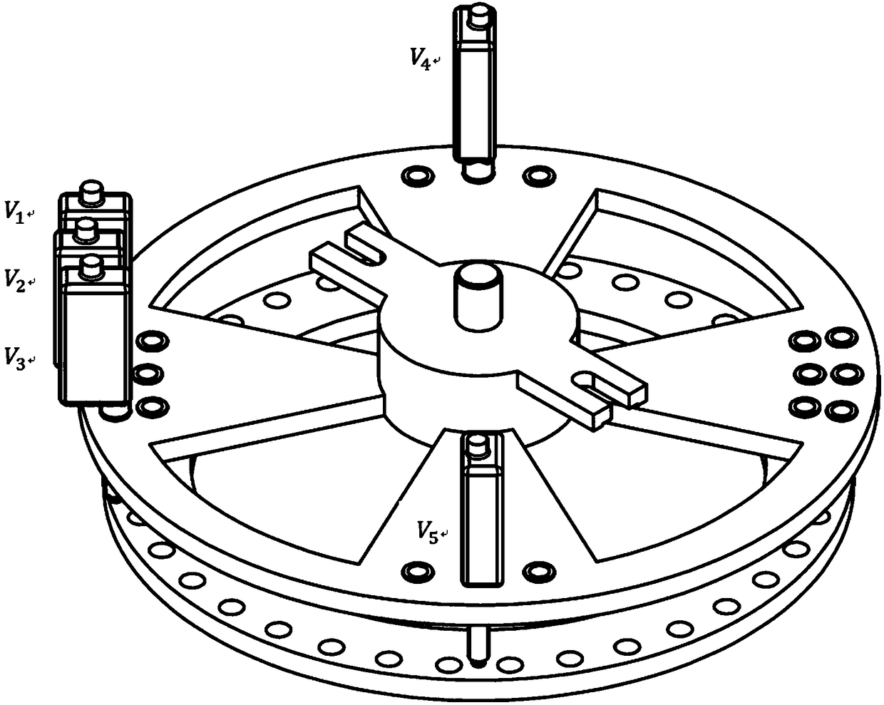
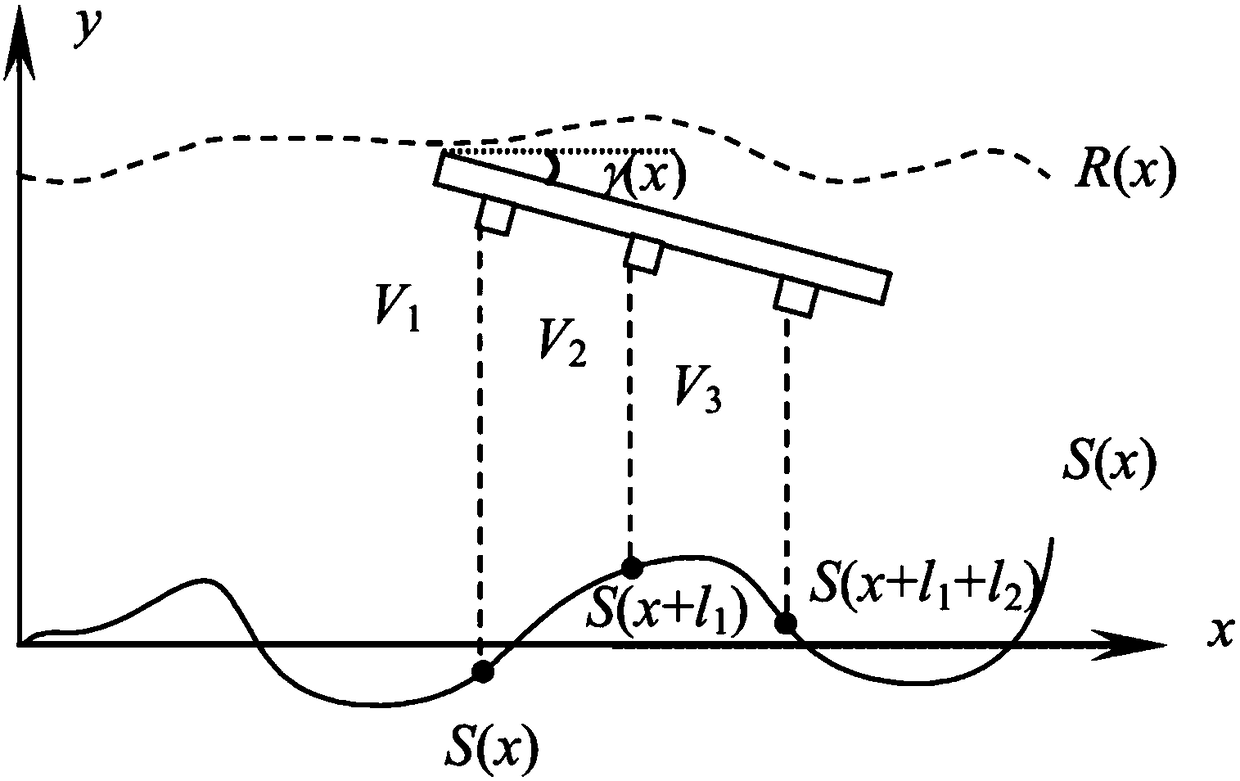
[0021] Step A: Install at least five touch sensors 8 on the sensor fixture 10, wherein three touch sensors 8V 1 , V 2 and V 3 It is a measuring sensor, which can be installed in any row of jacks in any group, but must be installed in the same row; the fourth contact sensor 8V 4 mounted on V 2 In the socket with an angle of 90°, and located in the center socket; the fifth touch sensor 8V 5 mounted on V 2 In the socket with an included angle of 90°, and located in the center socket, it is connected to V 4 Symmetrical; where V 1 , V 2 The enclosed central angle is α 1 , V 2 , V 3 The enclosed central angle is α 2 , where: α 1 = α 2 = α, and N is the number of measuring points on the DUT;

[0022] Step B: Set the inclination angle of the axis between the workpiece to be tested and the surface of the sensor fixture 10 as θ, and the rotation angle during each measuremen...


PUM


Abstract

The invention provides a method for measuring the shape error of a circular plane in situ, which is implemented based on a large circular plane shape error in-situ measurement system. The in-situ measurement system comprises a posture adjusting part, a rotating part, and a measuring part. The posture adjusting part comprises a posture adjusting table, a posture adjusting motor, and an adapter plate. The rotating part comprises a rotating index plate base and a high-precision rotating index plate. The measuring part comprises a sensor fixture, sensor holders, contact sensors and supporting equipment thereof. The application of a three-point method in measurement of the shape error of a circular plane is realized, and an algorithm for measuring the shape error of a circular plane in situ based on the three-point method is improved. Through the method, the shape error of a circular plane can be measured in situ, the processing time of parts is reduced greatly, and the influence of multiple times of clamping on the precision of parts is reduced.

Description

technical field [0001] The invention belongs to the on-site measurement method of flatness error, and can be widely used in the flatness measurement of annular parts of major engineering equipment such as aeroengines and centrifugal compressors. Background technique [0002] When assembling mechanical parts, the shape error of the assembly interface is very important. The shape error often affects the contact stiffness and assembly accuracy. In order to accurately control the performance of the assembly, it is necessary to test the shape error of the part. At present, large circular planes widely exist in many major equipments in our country, such as high-pressure and low-pressure turbine shafts in aero-engines, high-pressure compressor drums and other parts, there are a large number of circular planes. Assembly problems are closely related to the detection of shape errors, and the workpiece cannot be rotated freely during the assembly process. Therefore, in-situ measurement...

Claims


Application Information

Patent Timeline
Patent Type & Authority Patents(China)
IPC IPC(8): G01B21/20G01B21/30
CPCG01B21/20G01B21/30
Inventor 孙清超刘鑫王珏孙伟姜英杰索嘉琪
Owner DALIAN UNIV OF TECH
Why Eureka
Try Eureka