Optical microscope beam splitter device

An optical microscope and beam splitter technology, applied in microscopes, optics, measuring devices, etc., can solve problems such as the improvement of beam splitter devices, and achieve the effects of compact structure, improved utilization, and easy installation.

Inactive Publication Date: 2015-01-07
CHONGQING INST OF GREEN & INTELLIGENT TECH CHINESE ACADEMY OF SCI
View PDF8 Cites 6 Cited by
  • Summary
  • Abstract
  • Description
  • Claims
  • Application Information

AI Technical Summary

Problems solved by technology

Patent CN 101738716B discloses an optical microscope, which has been modified for the microscope bracket body, and has not made any improvement on the beam splitter device

Method used


Image

  • Optical microscope beam splitter device
  • Optical microscope beam splitter device
  • Optical microscope beam splitter device

Examples


Embodiment Construction

[0019] Hereinafter, preferred embodiments of the present invention will be described in detail with reference to the accompanying drawings. It should be understood that the preferred embodiments are only for illustrating the present invention, but not for limiting the protection scope of the present invention.

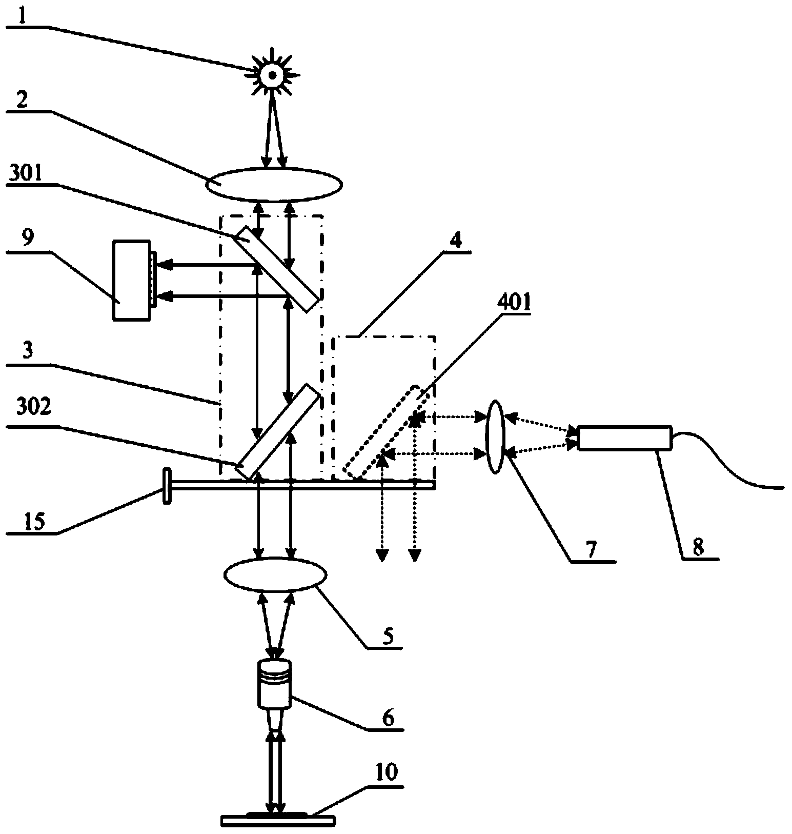
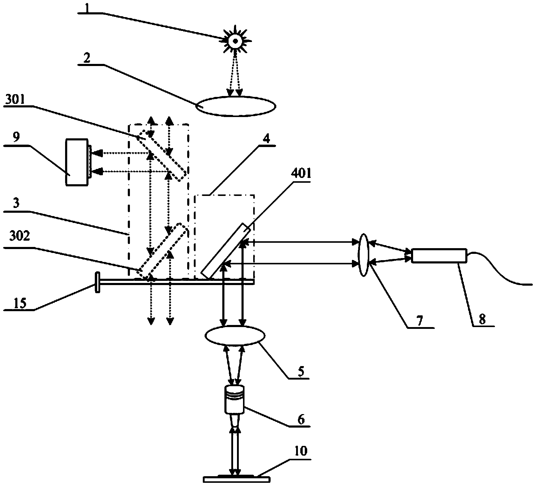
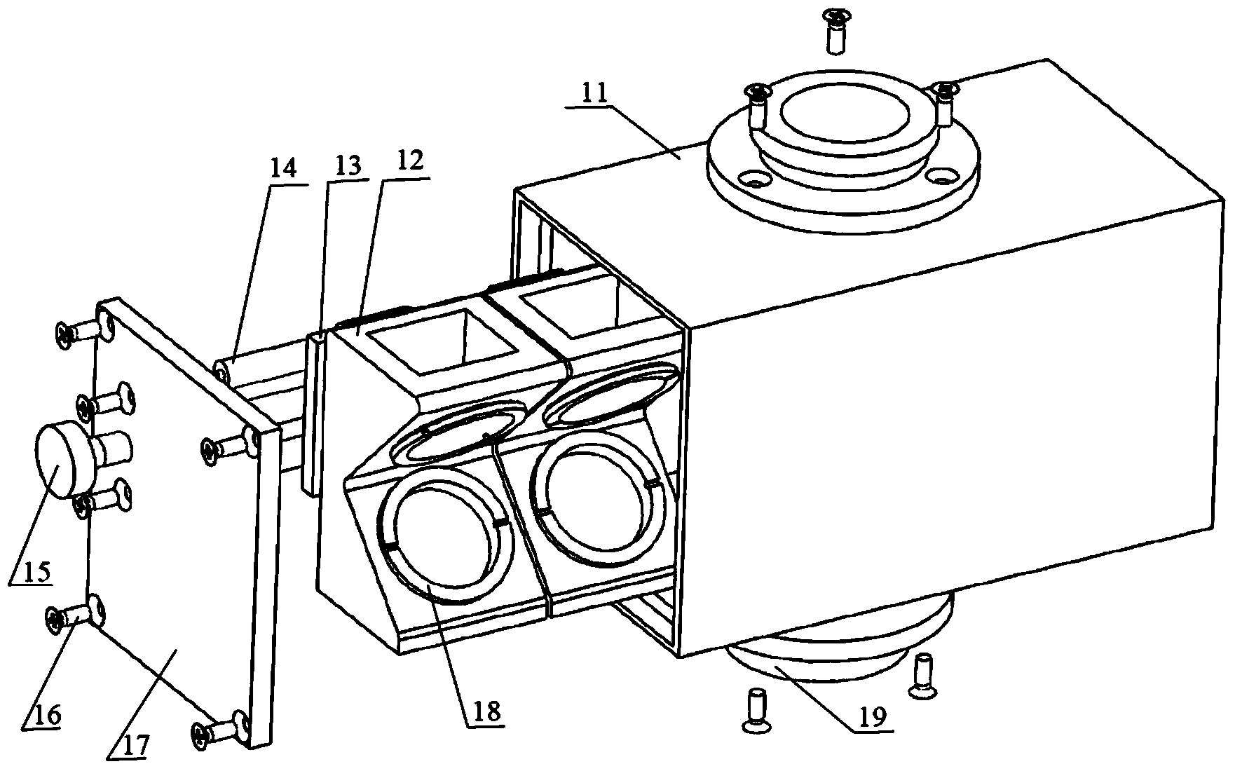
[0020] Such as Figure 1-Figure 4 As shown in the figure, 1 is a white light source; 2 is a collimating mirror; 3 is a white light imaging observation module; 301 is a beam splitter I; 302 is a beam splitter II; 4 is a spectrum measurement module; 401 is a beam splitter III; 5 is the object lens; 6 is the objective lens assembly; 7 is the condenser; 8 is the spectrometer probe assembly; 9 is the CCD detector; 10 is the sample stage; 11 is the beam splitter shell; 14 is a linear guide rail; 15 is a tie rod; 16 is a connecting screw; 17 is a cover plate of a beam splitter; 18 is a pressure ring of a beam splitter; 19 is a snap ring of a beam splitter.

[0021] The opti...


PUM

PropertyMeasurementUnit
angleaaaaaaaaaa

Abstract

The invention discloses an optical microscope beam splitter device which comprises a beam splitter shell and a beam splitter cover plate. The beam splitter cover plate is used for guaranteeing that space in the beam splitter shell does not leak light. Two sets of beam splitting sheet fixing frames are arranged in the beam splitter shell in parallel, one set is used for white light imaging observation, and the other set is used for spectral measurement. A switching mechanism used for switching the two sets of beam splitting sheet fixing frames is further arranged in the beam splitter shell. An in-situ observation white light imaging focus point and a laser in-situ measurement point of a measured sample are kept consistent by switching a double-beam-splitting-sheet white light imaging observation module and a spectral measurement full-reflection mirror module, the utilization ratio of light intensity of incoming lasers and the efficiency of collecting light signals (raman scattering light or fluorescent light) from the sample are improved, and the testing space resolution and testing sensitivity are improved.

Description

technical field [0001] The invention belongs to the field of optical microscope instrument design and microscopic spectrum measurement, and in particular relates to an optical microscope beam splitter device for fast white light imaging observation and high-sensitivity / high-spatial-resolution in-situ spectrum measurement of a portable spectrometer. Background technique [0002] The optical microscope organically combines microscopic technology, photoelectric conversion technology, and liquid crystal screen technology to display the fine structure of the sample surface. It has been widely used in optical measurements in the fields of physics, chemistry, biology, materials, and physical evidence. Beam splitter is one of the important optical components for image observation in optical microscope. Ordinary optical microscopes usually only install a beam splitter at an angle of 45 degrees to the incident light, which divides the incident light into two beams of transmitted and r...

Claims


Application Information

Patent Timeline
Patent Type & Authority Applications(China)
IPC IPC(8): G02B21/00G02B21/36G01N21/65G01N21/64
CPCG01N21/6458G01N21/65G02B21/00G02B21/368
Inventor 陈昭明张炜汤冬云张华方绍熙谢婉谊何石轩王雅冠刘崇武刘玉龙
Owner CHONGQING INST OF GREEN & INTELLIGENT TECH CHINESE ACADEMY OF SCI
Why Eureka
Try Eureka