Heating device for micro-area controllable nano functional material synthesis

A nano-functional, heating device technology, applied in the direction of single crystal growth, chemical instruments and methods, from condensed steam, etc., can solve the problems of single synthesis method, large volume, poor controllability, etc., and achieve small synthesis device, simple and compact structure , Ease of movement

Inactive Publication Date: 2011-01-26
HEFEI UNIV OF TECH
View PDF0 Cites 1 Cited by
  • Summary
  • Abstract
  • Description
  • Claims
  • Application Information

AI Technical Summary

Problems solved by technology

[0004] In order to solve the problems of bulky, energy-consuming, time-consuming, single synthesis method and poor controllability of nano functional material synthesis equipment, the present invention provides a micro-zone controllable nano functional material synthesis heating device

Method used


Image

  • Heating device for micro-area controllable nano functional material synthesis
  • Heating device for micro-area controllable nano functional material synthesis
  • Heating device for micro-area controllable nano functional material synthesis

Examples


Embodiment 1

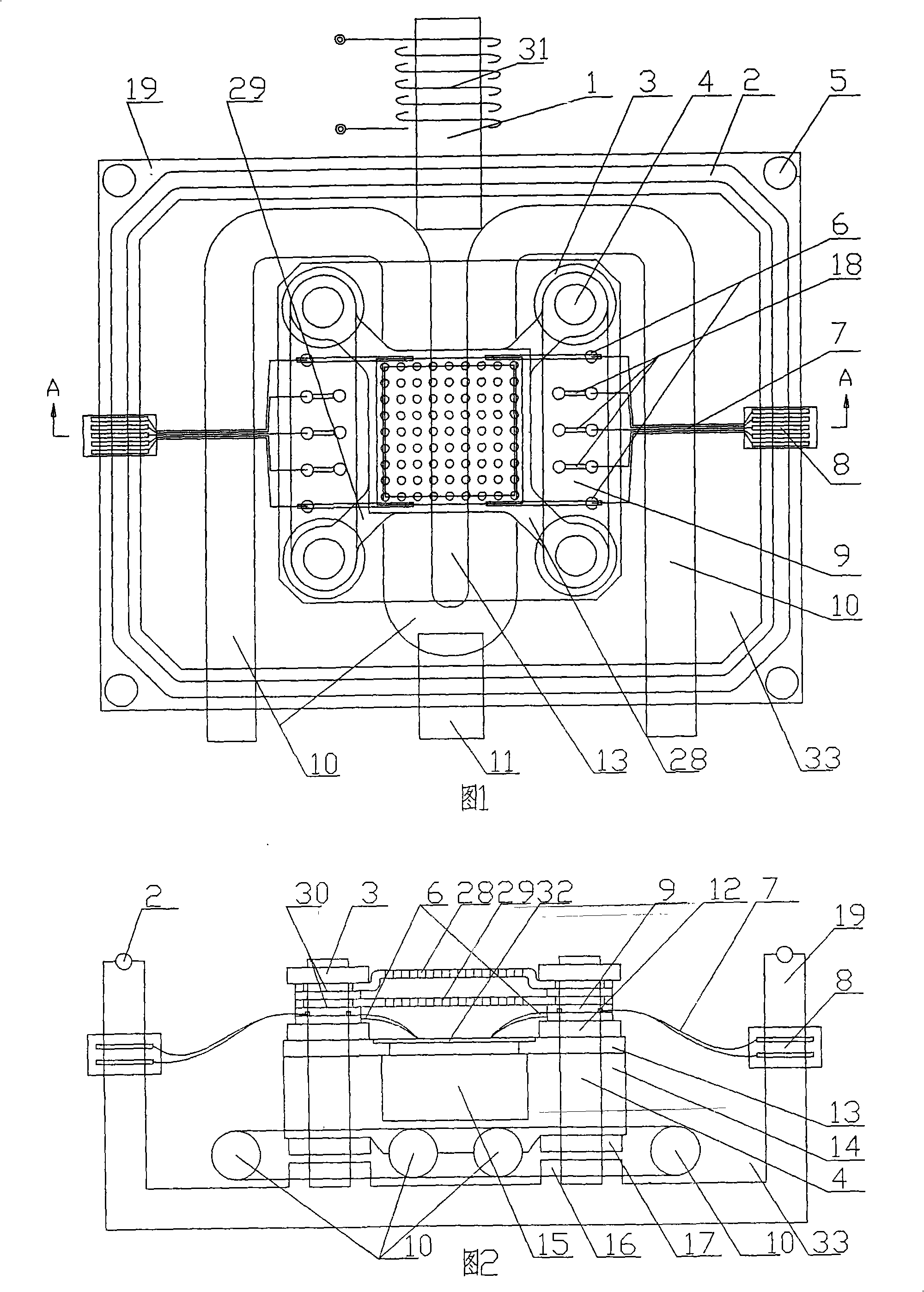
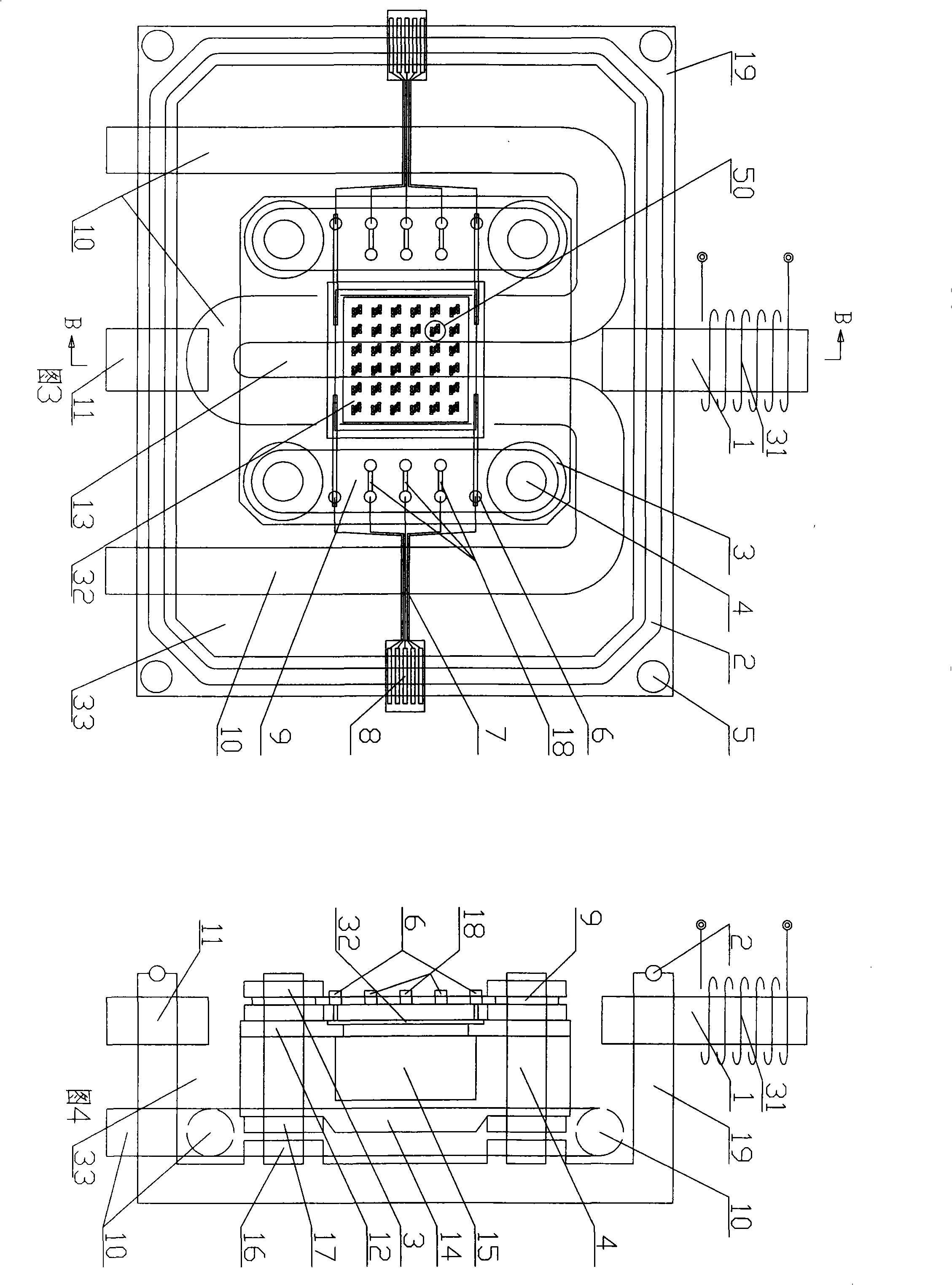
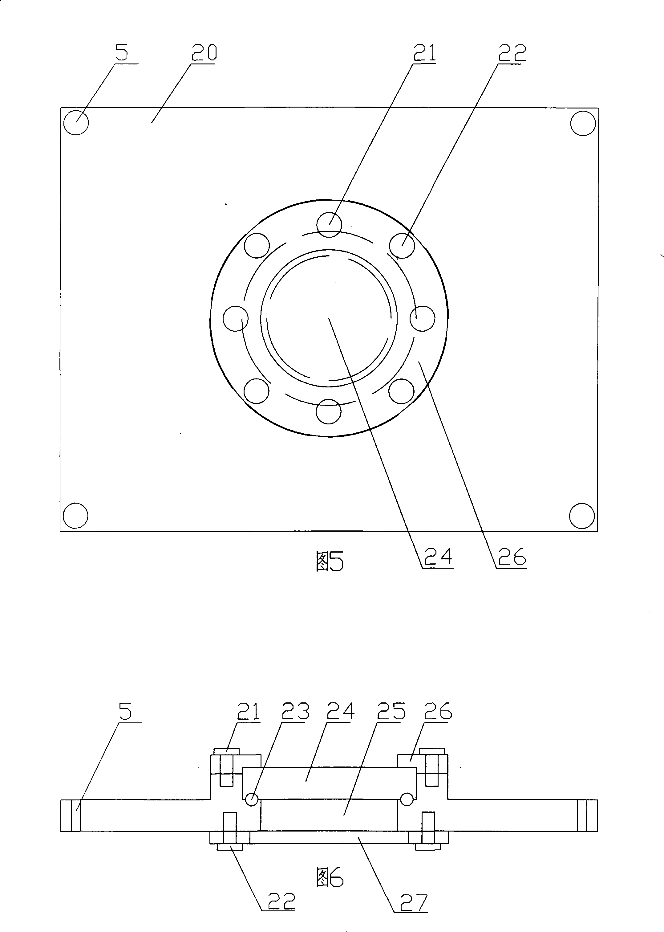
[0036] Referring to Fig. 1, Fig. 2, Fig. 3 and Fig. 4, the present invention comprises rectangular box body 19 and lid 20; The length, width and height of rectangular box body 19 are respectively 86 millimeters, 68 millimeters, 30 millimeters.

[0037] The corresponding two side walls of the rectangular box body 19 are respectively provided with an air inlet interface 1 and an air outlet interface 11, and the corresponding other two side walls are respectively provided with a wire interface 8; There is an air inlet coil 31 that is 3-5 centimeters (cm) long.

[0038] A rectangular heat dissipation base 14 is fixedly installed in the middle part of the box body 19 through four columns 4 on four corners, and the lower end of the column 4 is fixedly installed in the base positioning hole 16 through the lower positioning nut 7; the middle part of the heat dissipation base 14 is the lower Concave heat dissipation cavity 15; the length, width and height of the rectangular heat dissip...

Embodiment 2

[0049] Electromagnet 39 is loaded into the cooling cavity 15 and the observation window hole 25 of the upper cover. Others are with embodiment 1.

[0050] Close the gas path air valve 38 and the molecular pump valve 43, open the mechanical pump valve 41 and the mechanical pump 42, and vacuumize the working chamber 33. Observe the indication of the barometer 40 in the working chamber, and when it drops to 0Pa, close the valve 41 of the mechanical pump, open the valve 43 of the molecular pump, and the valve 44 of the molecular pump to continue vacuuming the working chamber 33 until the reaction condition is reached. The gas path valve 38 is opened, and the reaction gas A enters from the gas path interface 36 , and flows into the working chamber 33 after the gas flow meter 37 adjusts the gas flow.

[0051] A constant DC voltage of 130V-220V is applied between the upper plate 28 and the lower plate 29 to promote ionization and activation of the reactive gas. Apply current to the...

Embodiment 3

[0056] A set of wires is used to connect the probes 6 to the resistance lines 35 of the circuits 50 in the odd columns on the silicon chip 32 , and another group of wires is used to connect the probes 6 to the resistance lines 35 of the circuits 50 in the even columns on the silicon chip 32 . Connect the upper plate 28 and the lower plate 29 with the wire connector 8 and apply positive and negative DC voltages respectively. Heat radiation base cavity 15, loam cake cavity 25 pack electromagnet 39, and connect it with wire connector 8 with silver glue, electric wire.

[0057] Others are with embodiment 1.

[0058] Close the gas path air valve 38 and the molecular pump valve 46, open the mechanical pump valve 41 and the mechanical pump 42, and vacuumize the working chamber 33. Observe the indication of the barometer 40 in the working chamber, and when it drops to 0Pa, close the valve 41 of the mechanical pump, open the valve 43 of the molecular pump, and the valve 44 of the mole...


PUM

PropertyMeasurementUnit
thicknessaaaaaaaaaa

Abstract

The invention relates to a microdomain controllable nanometer functional material synthetic heating device, which solves the problems of enormous volume, dissipation energy, consuming and single synthetic method of the existing nanometer functional material synthetic device. The heating device comprises a rectangle box body and a box cover. Two side walls which are corresponding to the box body are respectively provided with an entering air port connector and an outgoing gas connector. The other two side walls are respectively provided with an electric wire connector. The interior of the box body is sequentially provided with a cooling water pipe, a heat dissipation foundation bed, a workbench, a junction board, a lower panel and an upper panel from bottom to top. The middle of the workbench is provided with a stepped hole which is big at the upper part and small at the lower part. The junction board is provided with a connector lug and a probe. The heating device has small volume; the volume is 240dm3, thereby the heating device is convenient to be moved; the consuming time of vacuumizing is shortened to 5-15 minutes; the heating up and cooling time and the height are controllable; the whole temperature increasing and decreasing course can be finished in 2-10 minutes; the nanometer structure can be prepared on a silicon base with an external circuit; a plurality of nanometer structures can be integrated on the same under layer. The consumption of water, electric and gas reduced to 5-10% of the former.

Description

technical field [0001] The invention relates to a nano functional material synthesis equipment, in particular to a micro-electrode micro-heating device for controlling the local synthesis of nano functional materials. Background technique [0002] Nano-functional materials have very important applications in the new generation of nano-optoelectronics, sensing, storage and other devices. In order to achieve the purpose of device application, it is first necessary to realize the controllable synthesis of nanomaterials, such as controlling the structure, morphology and orientation of nanomaterials according to the requirements of device applications. It must be pointed out that the positioning and directional synthesis of nanomaterials is a difficult technology at present, and it is also a key technology in the synthesis of nanomaterials. At present, there are a variety of synthesis methods for low-dimensional nanomaterials, involving many physical and chemical means, the most...

Claims


Application Information

Patent Timeline
Patent Type & Authority Patents(China)
IPC IPC(8): C30B25/00C30B23/00
Inventor 揭建胜胡治中吴春艳王莉于永强
Owner HEFEI UNIV OF TECH
Why Eureka
Try Eureka