Device for testing solid-state lithium battery

A battery testing, solid-state lithium technology, applied in measurement devices, measuring electricity, measuring electrical variables, etc., can solve the reading drift of solid-state lithium battery expansion force sensors, lack of in-situ stress-strain characterization methods, electrode/electrolyte interface stress- Strain change process is not clear and other problems, to achieve the effect of in-situ observation

Pending Publication Date: 2021-09-24
TIANJIN UNIV
View PDF10 Cites 1 Cited by
  • Summary
  • Abstract
  • Description
  • Claims
  • Application Information

AI Technical Summary

Problems solved by technology

Since the current interface research of solid-state lithium batteries is in its infancy, the stress-strain change process of the electrode / electrolyte interface is still unclear, and there is a lack of effective in-situ stress-strain characterization methods. The problems encountered in the process of testing solid-state lithium batteries include: But not limited to: solid-state lithium battery charging / discharging is the release of powder particles that pollute the mirror or observation window, making it difficult to continuously obtain clear images, and the sensor readings used to collect the expansion force of solid-state lithium batteries drift severely, and this drift is related to temperature or The battery itself has nothing to do, and it is suspected to be related to the current collector holding the lithium battery itself, etc.

Method used


Image

  • Device for testing solid-state lithium battery
  • Device for testing solid-state lithium battery

Examples


Embodiment Construction

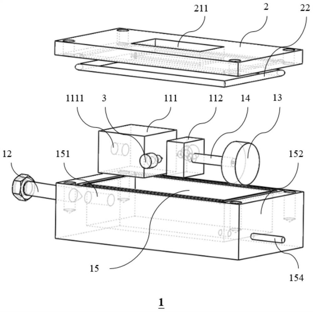
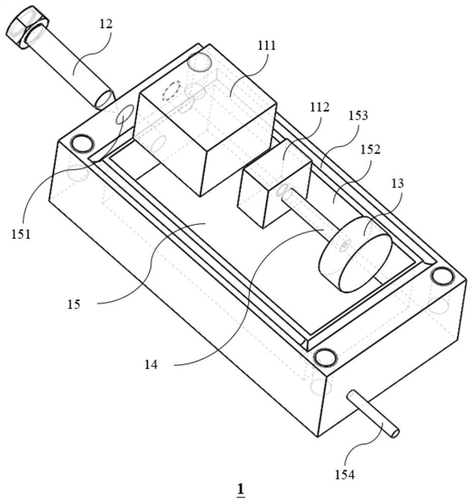
[0018] The technical solutions of the present invention will be described in detail below in conjunction with specific embodiments and accompanying drawings. The examples described here are specific implementations of the present invention and are used to illustrate the concept of the present invention; these descriptions are all explanatory and exemplary, and should not be construed as limiting the implementation of the present invention and the protection scope of the present invention . In addition to the embodiments described here, those skilled in the art can also adopt other obvious technical solutions based on the claims of the application and the contents disclosed in the specification, and these technical solutions include adopting any modifications made to the embodiments described here. Obvious alternatives and modified technical solutions. It should be understood that, unless otherwise specified, for ease of understanding, the following descriptions of the specifi...


PUM

PropertyMeasurementUnit
thicknessaaaaaaaaaa

Abstract

The invention discloses a device for testing a solid-state lithium battery. The device comprises a box body, a first current collector, a second current collector, a bolt, a connecting rod, a first sensor, a sealing cover plate and at least one tab for electrically connecting components in the box body with the outside. Threaded holes are formed in one side wall, in the length direction, of the box body and the first current collector, so that the first current collector can be horizontally moved through rotation of a bolt outside the box body, and a battery to be detected is suspended and clamped between the first current collector and a second current collector which are arranged in the length direction of the box body. The other end of the second current collector is sequentially connected with the connecting rod and the first sensor, so that the first sensor is propped against the inner surface of the other side wall of the box body to test the pressure output by the solid-state lithium battery during operation; wherein the sealing cover plate is provided with a transparent baffle plate for observing the operation of the battery to be detected, and the baffle plate is made of quartz glass, polytetrafluoroethylene or sapphire materials.

Description

technical field [0001] The invention relates to the technical field of battery testing, in particular to a device for testing solid-state lithium batteries. Background technique [0002] In traditional commercial batteries today, the use of liquid electrolytes ensures the fast movement of lithium ions and the good performance of the batteries. However, with the development of science and technology, especially the rapid development of electric vehicles and large-scale energy storage industries, the energy density of commercial lithium-ion batteries has been unable to meet the current needs of use. At the same time, the liquid electrolyte is prone to volatilization and leakage during the long cycle, resulting in a decrease in battery performance. In addition, during the charging and discharging process of the battery, the uneven deposition of Li+ on the surface of the lithium electrode leads to the rapid growth of lithium dendrites, and the battery is prone to safety hazards...

Claims


Application Information

Patent Timeline
Patent Type & Authority Applications(China)
IPC IPC(8): G01R31/378G01R31/385G01L5/00
CPCG01R31/378G01R31/385G01L5/00
Inventor 李传崴杨思源王志勇王世斌李林安
Owner TIANJIN UNIV
Why Eureka
Try Eureka