Analog heat source chip and manufacturing method thereof

A heat source and chip technology, applied in the field of simulating heat source chips and their production, can solve the problems of complicated infrared thermal imaging test system equipment, difficult heat source chip temperature, high price, etc., to achieve high-power heating, simple structure, and measurement process. handy effect

Active Publication Date: 2019-02-05
SOUTHWEST CHINA RES INST OF ELECTRONICS EQUIP
View PDF4 Cites 5 Cited by
  • Summary
  • Abstract
  • Description
  • Claims
  • Application Information

AI Technical Summary

Problems solved by technology

[0005] The purpose of the present invention is to overcome the following defects in the prior art: the existing analog heat source chip only has a simple heating function, and the performance of the microchannel radiator must be analyzed by means of thermocouples or infrared thermal imaging techniques; and thermocouples generally use It is difficult to accurately analyze the temperature of the simulated heat source chip in different areas on the surface of the radiator through contact measurement of temperature; the infrared thermal imaging test system is complex in equipment, expensive in price, complicated in operation and poor in practicability

Method used


Image

  • Analog heat source chip and manufacturing method thereof
  • Analog heat source chip and manufacturing method thereof
  • Analog heat source chip and manufacturing method thereof

Examples


Embodiment approach

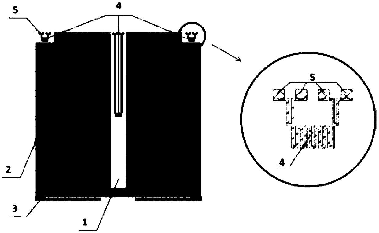
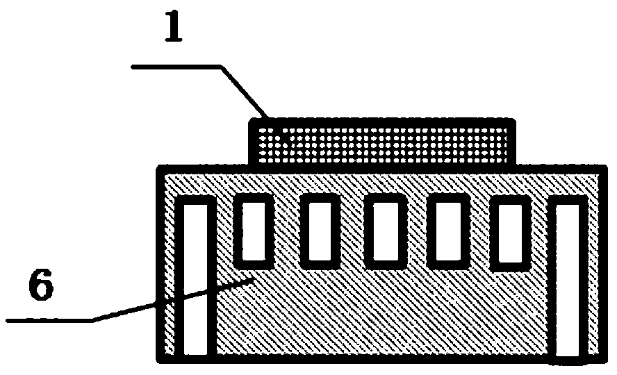
[0046] Such as Figure 1-3 As shown, an analog heat source chip 1 has an analog heat source resistor 2 and a temperature sensor 4 on its surface, and both the analog heat source resistor 2 and the temperature sensor 4 are thin film planar resistors.

[0047]The temperature coefficient of resistance of metal is linear, and the resistance change can be measured by the four-wire method to characterize the temperature change of the metal. This method is widely used in metal temperature sensors. In the above-mentioned technical scheme, the simulated heat source resistance 2 is evenly distributed on the surface of the entire simulated heat source chip 1 to realize uniform heat generation, and the temperature sensor 4 can be distributed at any position on the surface of the simulated heat source chip 1, and its actual distribution position is based on the thin film microchannel heat sink. The heat dissipation structure is determined. During the test, the simulated heat source chip 1...

Embodiment

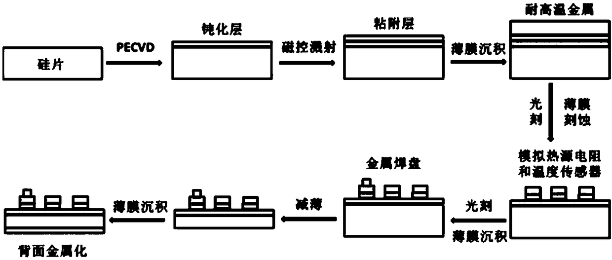
[0071] Such as Figure 1-3 As shown, a simulated heat source chip 1 includes a welding layer, a substrate, a passivation layer, an adhesion layer and a metal film layer, the welding layer is arranged on the lower surface of the substrate, and the passivation layer is arranged on the lower surface of the substrate. On the upper surface of the substrate, the adhesion layer is arranged on the surface of the passivation layer, and the metal film layer is arranged on the surface of the adhesion layer; the metal film layer is composed of an analog heat source resistance 2 and a temperature sensor 4, A heat source pad 3 and a sensor pad 5 are also provided on the metal film layer.

[0072] The material of the substrate is silicon, the material of the passivation layer is SiN, the material of the adhesion layer is TiN, the material of the soldering layer is Au, and the material of the metal film layer is W. The thickness of the substrate was 100 micrometers. The simulated heat sourc...


PUM

PropertyMeasurementUnit
Resistanceaaaaaaaaaa
Thicknessaaaaaaaaaa

Abstract

The invention discloses an analog heat source chip. The analog heat source chip is characterized in that the surface of the chip has analog heat source resistors and temperature sensors; and the analog heat source resistors and the temperature sensors are all thin film planar resistors. Through the integration of the analog heat source resistors and the temperature sensors, large power heating canbe realized, and the temperature gradient change situations of the whole chip can be accurately and in real time measured; through the adjustment of the positions of the temperature sensors, the in-situ measurement of the heat dissipation characteristics in different areas of a microchannel heat dissipator can be realized, so that the hot fluid performance of the heat dissipator can be accuratelyanalyzed; and the chip is simple in structure and manufacturing technology and convenient in measuring process.

Description

technical field [0001] The invention relates to the technical field of microelectronic heat dissipation, in particular to an analog heat source chip and a manufacturing method thereof. Background technique [0002] Micro-channel heat dissipation technology is a forced heat exchange cooling technology. By integrating the micro-channel heat sink into the electronic system, the heat dissipation efficiency can be greatly improved. Compared with passive cooling and traditional active cooling, micro-channel cooling technology has unique advantages. This is because: on the one hand, the microchannel heat dissipation technology using liquid as the cooling medium can achieve high heat transfer density; on the other hand, the convective heat transfer coefficient of liquid flow heat transfer in the microchannel is inversely proportional to the equivalent size of the channel, While reducing the equivalent size of the channel, it can not only significantly improve the heat exchange effe...

Claims


Application Information

Patent Timeline
IPC IPC(8): H01L23/473G01M99/00
CPCG01M99/005G01M99/008H01L23/473
Inventor 张剑卢茜李阳阳向伟玮蒋苗苗徐秀琴
Owner SOUTHWEST CHINA RES INST OF ELECTRONICS EQUIP
Why Eureka
Try Eureka