Supercharge Your Innovation With Domain-Expert AI Agents!

Current limit control in hot swap controllers

A current-limiting and power-controlling technology, applied in control/regulation systems, AC-DC network circuit layout, DC power input conversion to DC power output, etc., can solve the problem of affecting circuit operation, disturbing power supply operation, affecting power supply load or circuit operation And other issues

Inactive Publication Date: 2017-09-12
ANALOG DEVICES GLOBAL
View PDF5 Cites 4 Cited by
  • Summary
  • Abstract
  • Description
  • Claims
  • Application Information

AI Technical Summary

Problems solved by technology

[0003] These inrush currents can disrupt the operation of the power supply, potentially tripping protections in the power supply
In addition, inrush currents may introduce disturbances in the power supplied to other loads connected to the source, which may affect the operation of the circuit
Also, if a newly introduced load fails, that failure may also affect the operation of the power supply and other loads or circuits connected to the power supply

Method used


Image

  • Current limit control in hot swap controllers
  • Current limit control in hot swap controllers
  • Current limit control in hot swap controllers

Examples


example 1

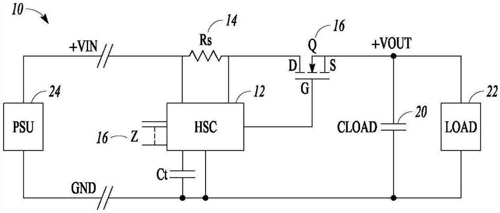
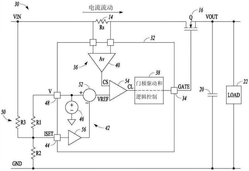
[0044] Example 1 includes a subject for controlling an electronic switch between a power source and a load (for example, a device, equipment, or machine), the device including: a first device pin configured to communicate with the electronic switch; a sensing circuit, Is configured to be connected to the input voltage and measure the current of the load; a control circuit is configured to communicate with the sensing circuit and the electronic switch, and is configured to use a current limiting signal to control the operation of the electronic switch; and limit A current circuit is configured to communicate with the control circuit, and is configured to generate the current limit signal indicating current limit and automatically adjust the current limit signal according to changes in at least one of the input voltage and the output voltage.

[0045] In Example 2, the subject of Example 1 may optionally include: wherein the sensing circuit is configured to output a voltage proporti...

example 10

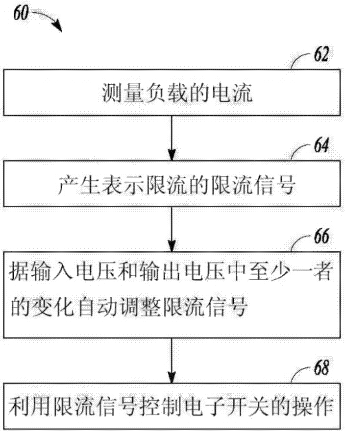
[0053] Example 10 includes subjects for controlling electronic switches between a power source and a load (for example, methods and devices for performing actions, machine-readable media including instructions (instructions when executed by a machine cause the machine to perform actions) or are configured to Device for performing actions), the device comprising: measuring the current of the load; generating a current-limiting signal indicating current-limiting; automatically adjusting the current-limiting signal according to changes in at least one of the input voltage and the output voltage; and using all The current limiting signal controls the operation of the electronic switch.

[0054] In Example 11, the subject matter of Example 10 optionally includes:

[0055] Wherein generating a current-limiting signal representing current-limiting and automatically adjusting the current-limiting signal according to changes in at least one of the input voltage and the output voltage includ...

example 18

[0065] Example 18 includes a subject (eg, a circuit) for controlling an electronic switch between a power source and a load, the circuit including: a first node configured to communicate with the electronic switch; a sensing circuit configured to be connected to an input voltage And measure the current of the load; a control circuit configured to communicate with the sensing circuit and the electronic switch, and configured to use a current limiting signal to control the operation of the electronic switch; and a current limiting circuit configured to communicate with The control circuit communicates and is configured to generate the current limit signal representing current limit and automatically adjust the current limit signal according to changes in at least one of the input voltage and the output voltage.

[0066] In Example 19, the subject matter of Example 18 optionally includes:

[0067] Wherein the sensing circuit is configured to output a voltage proportional to the measur...


PUM


Abstract

The invention relates to current limit control in hot swap controllers. In an example, a device for controlling an electronic switch between a power supply and a load includes a first device pin configured to be in communication with the electronic switch, a sensing circuit configured to be connected to an input voltage and to measure a current to the load, a control circuit configured to be in communication with the sensing circuit and the electronic switch, the control circuit configured to use a current limit signal to control operation of the electronic switch, and a current limit circuit configured to be in communication with the control circuit, the current limit circuit configured to generate the current limit signal representing a current limit and automatically adjust the current limit signal in response to a change in at least one of the input voltage and an output voltage.

Description

Technical field [0001] The present disclosure generally relates to a connection device capable of supplying electric power to an electrical load. Background technique [0002] There are situations where it is necessary to connect an electrical load to a power source that has been turned on. In this way, a large inrush current is generated due to the charging of the capacitive part of the load. The capacitive part can be actual or parasitic. [0003] These inrush currents can disrupt the operation of the power supply, which may trip the protective measures in the power supply. In addition, inrush current may introduce disturbances in the power supplied to other loads connected to the power source, and these disturbances may affect the operation of the circuit. In addition, if the newly introduced load fails, the failure may also affect the operation of the power supply and other loads or circuits connected to the power supply. [0004] In order to solve these problems, it is known...

Claims


Application Information

Patent Timeline
Patent Type & Authority Applications(China)
IPC IPC(8): G05F1/10H02H9/02
CPCG05F1/10H02H9/02H02H9/025H02J7/007184H02M3/155H02J4/00
Inventor M·D·奥沙利文A·托涅里
Owner ANALOG DEVICES GLOBAL
Features
  • R&D
  • Intellectual Property
  • Life Sciences
  • Materials
  • Tech Scout
  • Unparalleled Data Quality
  • Higher Quality Content
  • 60% Fewer Hallucinations
Learn More