Special cabinet for electrical equipment

A technology of electrical equipment and special cabinets, which is applied in the direction of electrical equipment casings/cabinets/drawers, electrical equipment structural parts, casings/cabinets/drawer parts, etc. Power repair time, lack of intelligent supervision and other issues, to achieve the effect of good heat dissipation and shock absorption, high safety, and reduce losses

Pending Publication Date: 2017-09-12
江苏亚楠电子科技有限公司
View PDF0 Cites 3 Cited by
  • Summary
  • Abstract
  • Description
  • Claims
  • Application Information

AI Technical Summary

Problems solved by technology

[0002] The vehicle-mounted equipment cabinet is used to carry and store the vehicle-mounted equipment, which is convenient for unified management and maintenance. The vehicle-mounted equipment is basically an electronic device that requires good temperature and humidity and a stable environment. The current vehicle-mounted equipment cabinet has low safety factor and poor heat dissipation effect. , Poor shock absorption effect and lack of intelligent supervision, especially in winter in the north and summer in the south, due to the large change in the external environment temperature, the internal temperature of the vehicle equipment cabinet also changes drastically, and the vehicle is relatively Bumps, there are often sudden brakes and starts, and the high temperature generated by the continuous work of many vehicle-mounted equipment in a small vehicle-mounted equipment cabinet is also amazing. This huge change in temperature and bumps will seriously affect the vehicle-mounted equipment in the vehicle-mounted equipment cabinet. The service life of electrical components; sometimes the power equipment cabinet encounters sudden problems and needs emergency repairs, and it is usually necessary to take and prepare tools before leaving the accident site. It takes time to prepare tools every time, and a large number of equipment will be prepared Tools that may not be used in practice will seriously delay the time for power repairs

Method used


Image

  • Special cabinet for electrical equipment

Examples


Embodiment Construction

[0015] The following will clearly and completely describe the technical solutions in the embodiments of the present invention with reference to the accompanying drawings in the embodiments of the present invention. Obviously, the described embodiments are only some, not all, embodiments of the present invention. All other embodiments obtained by persons of ordinary skill in the art based on the embodiments of the present invention belong to the protection scope of the present invention.

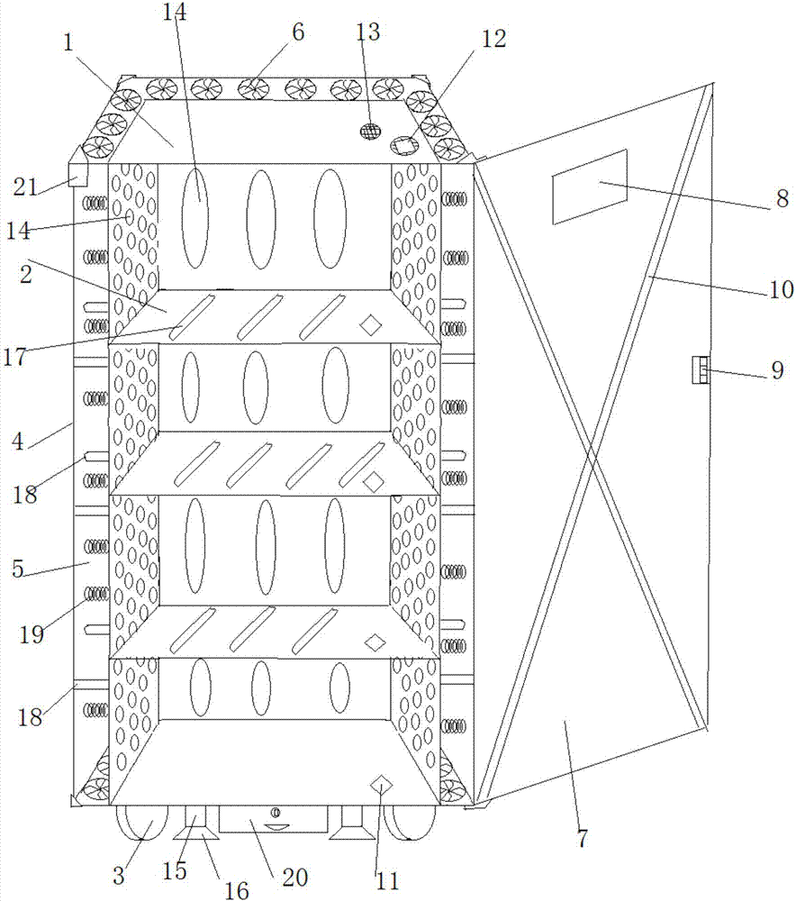
[0016] Such as figure 1 As shown, the special cabinet for electrical equipment described in this embodiment includes a cabinet body 1, a plurality of laminates 2 provided in the cabinet body 1, and a roller 3 provided at the bottom of the cabinet body 1, and the roller 3 is connected to the On the cabinet body 1, the cabinet body 1 is provided with a casing 4, and there is a gap 5 between the casing 4 and the cabinet body 1 as an air duct. The bottom and top of the gap 5 are provided with a p...


PUM


Abstract

The invention discloses a special cabinet for motor equipment, which comprises a cabinet body, a plurality of laminates arranged in the cabinet body and rollers arranged at the bottom of the cabinet body, the rollers are connected to the cabinet body through a shock absorber, the outer casing of the cabinet body is provided with a shell, and the outer shell There is a gap between the cabinet and the cabinet as an air duct. Multiple fans are installed at the bottom and top of the gap. The cabinet door is hinged with a display screen, password lock and reinforcing ribs. A temperature sensor is installed on the laminate. , the cabinet is equipped with a smoke sensor, buzzer, single-chip microcomputer and several ventilation holes. The fan, display screen, temperature sensor, smoke sensor and buzzer are all connected to the single-chip microcomputer. Secondary connections have retractable support legs and suction cups. It not only has high safety, but also has good heat dissipation and shock absorbing effects; it is also equipped with temperature and smoke alarm functions to ensure the safety of on-board equipment and minimize losses; it has a storage space for maintenance tools, which is convenient for maintenance and saves time.

Description

technical field [0001] The invention belongs to the field of installation cabinets for vehicle-mounted equipment, and in particular relates to special cabinets for motor equipment. Background technique [0002] The vehicle-mounted equipment cabinet is used to carry and store the vehicle-mounted equipment, which is convenient for unified management and maintenance. The vehicle-mounted equipment is basically an electronic device that requires good temperature and humidity and a stable environment. The current vehicle-mounted equipment cabinet has low safety factor and poor heat dissipation effect. , Poor shock absorption effect and lack of intelligent supervision, especially in winter in the north and summer in the south, due to the large change in the external environment temperature, the internal temperature of the vehicle equipment cabinet also changes drastically, and the vehicle is relatively Bumps, there are often sudden brakes and starts, and the high temperature genera...

Claims


Application Information

Patent Timeline
Patent Type & Authority Applications(China)
IPC IPC(8): H05K5/02H05K5/00H05K7/20G08B17/00
CPCH05K5/0217G08B17/00H05K5/0017H05K5/0213H05K5/0221H05K5/0234H05K5/0247H05K7/20145H05K7/20172
Inventor 陈恺张利洪
Owner 江苏亚楠电子科技有限公司
Why Eureka
Try Eureka