Chamfering machine for valve corners

A chamfering machine and edging technology, applied in the field of chamfering machines, can solve the problems of inability to chamfer, troublesome replacement process, time-consuming and laborious, etc., and achieve the effect of convenient chamfering and flexible use.

Pending Publication Date: 2017-09-15
JIANGSU SUGAO FLUID MACHINERY
View PDF7 Cites 5 Cited by
  • Summary
  • Abstract
  • Description
  • Claims
  • Application Information

AI Technical Summary

Problems solved by technology

However, the existing chamfering equipment is not flexible enough to chamfer with different angles. Once chamfering with different angles is required, the chamfering grinding wheel needs to be replaced. The replacement process is very troublesome and time-consuming.

Method used


Image

  • Chamfering machine for valve corners
  • Chamfering machine for valve corners

Examples


Embodiment Construction

[0016] The following will clearly and completely describe the technical solutions in the embodiments of the present invention with reference to the accompanying drawings in the embodiments of the present invention. Obviously, the described embodiments are only some, not all, embodiments of the present invention.

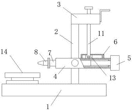
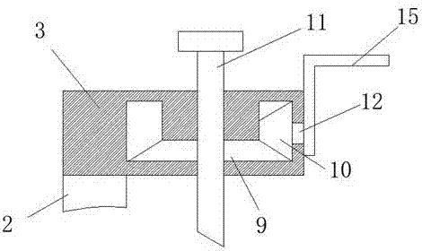
[0017] refer to Figure 1-2 , a chamfering machine for valve corners, including a base 1, a support rod 2 is vertically fixed on the top of the base 1, and a mounting shell 3 is fixed on one side of the support rod 2, and a mounting shell 3 and the base 1 are provided There is a hollow guide shell 4, and the hollow guide shell 4 is rotationally connected with the support rod 2, a hydraulic cylinder 5 is fixed on one side of the hollow guide shell 4, and a rectangular connection is fixed at one end of the piston rod of the hydraulic cylinder 5 located in the hollow guide shell 4 The rod 7, the end of the rectangular connecting rod 7 away from the hydraulic cylinder 5 ...


PUM


Abstract

The invention discloses a chamfering machine for valve corners. The chamfering machine for the valve corners comprises a base, a supporting rod is perpendicularly fixed on the top of the base, and an installing shell is fixed on one side of the supporting rod. A hollow guiding shell is arranged between the installing shell and the base, and the hollow guiding shell is rotatably connected with the supporting rod. A hydraulic cylinder is fixed on one side of the hollow guiding shell, and a rectangular connecting rod is fixed at the end, located in the hollow guiding shell, of a piston rod of the hydraulic cylinder. A chamfering grinding wheel is fixed at the end, away from the hydraulic cylinder, of the rectangular connecting rod. The chamfering grinding wheel is located on the side, away from the hydraulic cylinder, of the hollow guiding shell. A hollow limited block is fixed on the side, close to the installing shell, of the hollow guiding shell. According to the chamfering machine for the valve corners, the structures such as a clamp base, a hand rocking rod, a rotating shaft, a bevel gear, a bevel gear ring and an adjusting screw rod are matched to used so that the hollow guiding shell can be bodily rotated, and then the angle of the chamfering grinding wheel can be adjusted, the chamfered corners with different angles can be made, and usage is flexible.

Description

technical field [0001] The invention relates to the technical field of chamfering equipment, in particular to a chamfering machine used for valve corners. Background technique [0002] A valve is a device used to control the direction, pressure, and flow of a fluid in a fluid system. It is a device that enables or stops the flow of liquid, gas, and powder in piping and equipment and controls its flow. In the process of valve processing, the chamfering machine is often used to chamfer the edges and corners. [0003] When chamfering, workers usually install the valve to be chamfered on a liftable and rotatable fixture seat, and then use chamfering equipment to chamfer. However, the existing chamfering equipment is not flexible enough to chamfer with different angles. Once chamfering with different angles is required, the chamfering grinding wheel needs to be replaced. The replacement process is very troublesome and time-consuming. Contents of the invention [0004] The pur...

Claims


Application Information

Patent Timeline
Patent Type & Authority Applications(China)
IPC IPC(8): B24B9/00B24B41/06B24B47/12B24B47/14
CPCB24B9/00B24B41/06B24B47/12B24B47/14
Inventor 邱庆民
Owner JIANGSU SUGAO FLUID MACHINERY
Why Eureka
Try Eureka