welding bracket

A technology for welding brackets and welding surfaces, which is applied to the connection between superstructure subassemblies, superstructure subassemblies, vehicle parts, etc., and can solve the problems of difficult production of special-shaped beams, etc.

Active Publication Date: 2019-05-17
BAIC MOTOR CORP LTD
View PDF4 Cites 0 Cited by
  • Summary
  • Abstract
  • Description
  • Claims
  • Application Information

AI Technical Summary

Problems solved by technology

[0005] The invention provides a welded bracket to solve the problems caused by special-shaped beams in the prior art when filling the gaps between the rear longitudinal beam assembly structure, the rear section assembly structure of the sill inner panel, and the front extension plate assembly structure of the rear floor. Liang Cheng has a difficult problem

Method used


Image

  • welding bracket
  • welding bracket
  • welding bracket

Examples


Embodiment 1

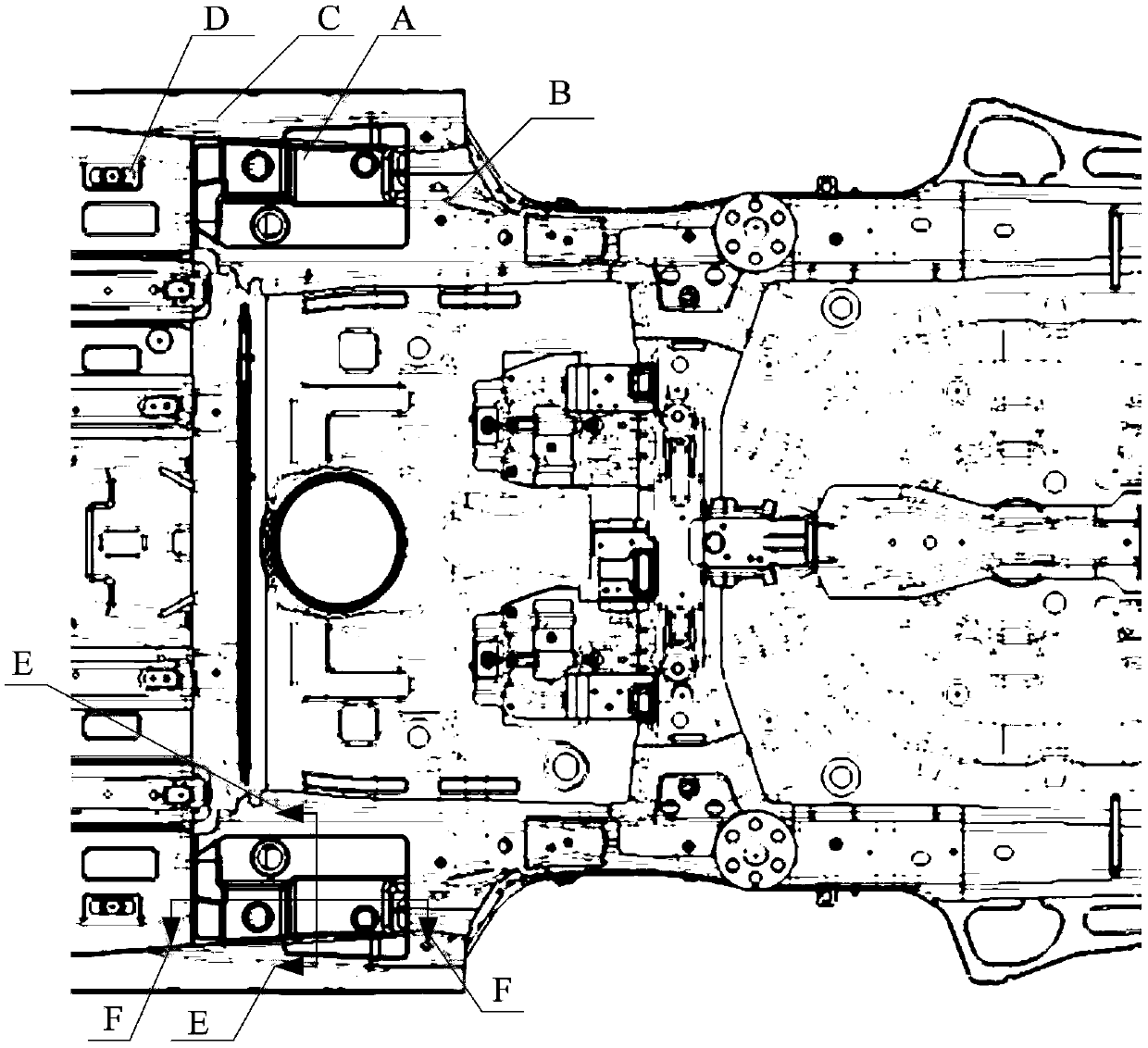
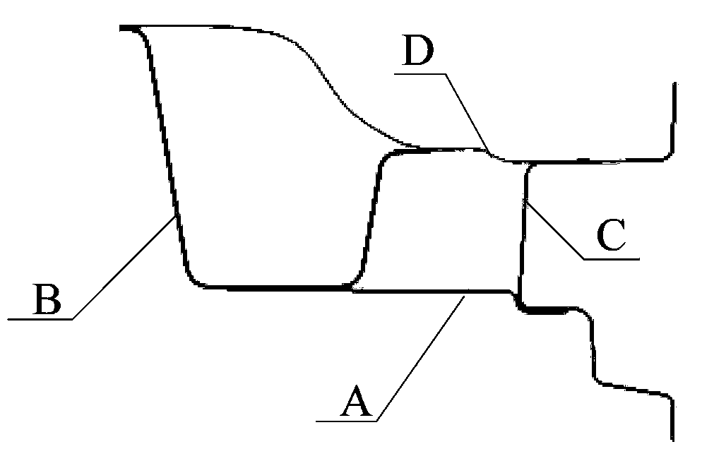
[0045] figure 1 The usage scene diagram of Embodiment 1 of the welding bracket provided by the present invention. refer to figure 1 , for vehicles with gaps between the rear longitudinal beam assembly structure B of the car body, the rear section assembly structure C of the door sill inner panel, and the front extension panel assembly structure D of the rear floor, the two provided by the present invention The welding bracket A is symmetrically arranged on the gap between the above three assembly structures to fill the gap between the above three assembly structures.

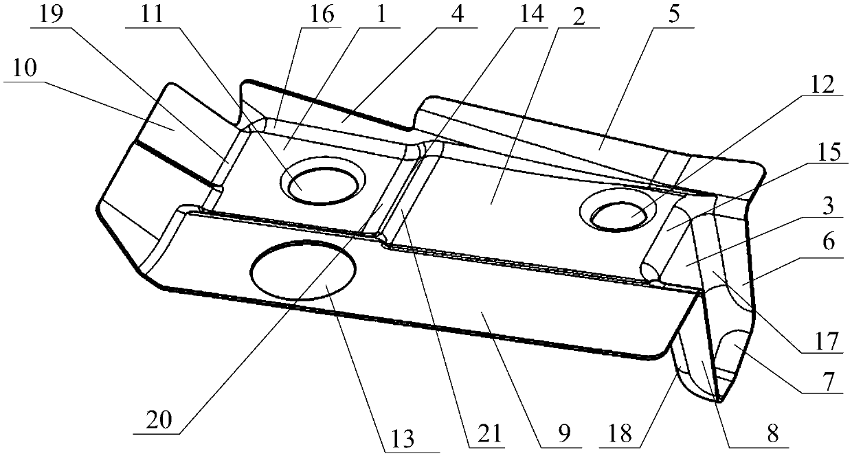
[0046] figure 2 For the structural schematic diagram of Embodiment 1 of the welding bracket provided by the present invention, refer to figure 2 . The welding space A provided by the present invention includes: three rectangular base surfaces and seven welding surfaces.

[0047] Among them, the connection relationship between the welding surface and the base surface is as follows:

[0048] The first recta...

Embodiment 2

[0059] This embodiment is carried out on the basis of Embodiment 1. refer to figure 2 , the welding bracket provided in this embodiment further includes: a first burring hole 11 , a second burring hole 12 and a third via hole 13 .

[0060] Wherein, the first flanging hole 11 is arranged on the first rectangular base surface 1, and the first flanging hole 11 is used as a rear positioning hole of the embrace on the assembly line.

[0061] The second flange hole 12 is arranged on the second rectangular base surface 2, the second flange hole 12 is used as the rear positioning hole of the skid on the painting production line, and the second flange hole 12 is also used as the rear suspension on the assembly line Positioning holes for module installation tooling.

[0062] The third via hole 13 is arranged on the sixth welding surface 9, and the third via hole 13 is used as a positioning hole for the rear floor assembly structure of the upper and lower vehicle bodies of the welding...


PUM


Abstract

The invention provides a welding bracket. The welding bracket comprises three rectangular base surfaces and seven welding surfaces, wherein the three rectangular base surfaces comprise a first rectangular base surface (1), a second rectangular base surface (2) and a third rectangular base surface (3); the seven welding surfaces comprise a first welding surface (4), a second welding surface (5), a third welding surface (6), a fourth welding surface (7), a fifth welding surface (8), a sixth welding surface (9) and a seventh welding surface (10); and the different welding surfaces are connected with the different base surfaces. The welding surfaces are used for welding the welding bracket to a rear stringer assembly structure, a sill inner plate rear section assembly structure and a rear floor front extension plate assembly structure of a vehicle body, among which gaps exist, so that the gaps among the three assembly structures are filled through the welding bracket provided by the invention. The welding bracket provided by the invention solves the problem that a special-shaped beam is difficult to produce when the special-shaped beam is adopted to fill the gaps in the prior art.

Description

technical field [0001] The invention relates to the technical field of machinery, in particular to a welding bracket. Background technique [0002] As the market demand for automobiles continues to diversify, the subdivision of automobile products continues to increase, and the number of vehicle models gradually increases. However, usually a variety of different models of automobiles are produced on the same production line. Therefore, some models produced on the same production line are affected by the structure of the suspension system, making the structure of the rear longitudinal beam assembly and the rear section assembly of the inner panel of the door sill The structure cannot be directly welded, resulting in gaps between the rear longitudinal beam assembly structure, the rear section assembly structure of the door sill inner panel and the front extension panel assembly structure of the rear floor. [0003] In the prior art, the rear longitudinal beam is generally pro...

Claims


Application Information

Patent Timeline
Patent Type & Authority Patents(China)
IPC IPC(8): B62D21/09B62D25/20B62D27/02
CPCB62D21/09B62D25/2027B62D27/02
Inventor 张虎梁岩
Owner BAIC MOTOR CORP LTD
Why Eureka
Try Eureka