Delivery and clearance device of circular bin

A silo and clearing technology, applied in the field of warehousing and discharging facilities, can solve the problems of investment cost, high power consumption, unavailability of the clearing machine for liquidity, and high operating costs, and achieves the effect of avoiding poor revolution.

Active Publication Date: 2017-09-15
MYANDE GRP CO LTD
View PDF7 Cites 5 Cited by
  • Summary
  • Abstract
  • Description
  • Claims
  • Application Information

AI Technical Summary

Problems solved by technology

[0007] The raw grain clearing machine in the prior art also uses the auger to discharge the material, and the clearing machine cannot be used for the meal bin with poor fluidity
In addition to the central outlet in the bin of the warehouse clearing machine, there are multiple outlets attached to the edge of the bin, and conveying equipment is equipped under each outlet, and the multiple conveying equipment is aggregated to one point, resulting in a large number of auxiliary equipment. Investment cost and large power consumption, high operating costs, high installation and maintenance costs
[0008] Based on the above reasons, the large-scale original granary and meal silo are currently built separately, resulting in very high investment costs; but the original granary and meal silo can be used in common in terms of technology
At present, there is no general warehouse-out equipment, which can not only discharge materials with good fluidity, but also discharge materials with poor fluidity

Method used


Image

  • Delivery and clearance device of circular bin
  • Delivery and clearance device of circular bin
  • Delivery and clearance device of circular bin

Examples


Embodiment Construction

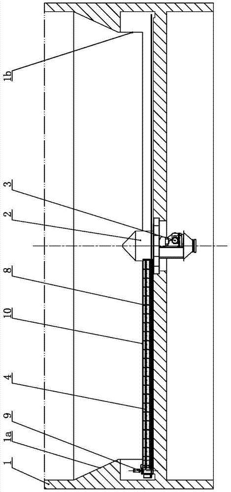
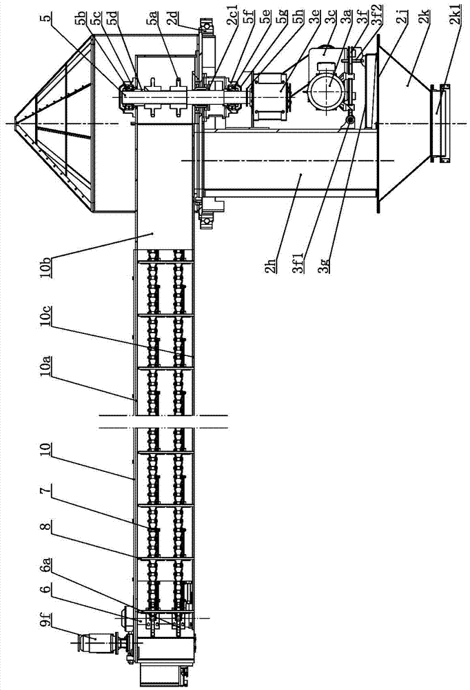
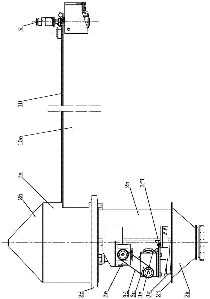
[0036] like Figure 1 to Figure 8As shown, the discharge and clearing device of the circular silo of the present invention includes a central rotation mechanism 2, a main drive mechanism 3, a scraper discharge mechanism 4, a girder mechanism 10 and a revolution walking mechanism 9, and the central rotation mechanism 2 is located at the bottom of the silo 1. Bottom center, the central rotating mechanism 2 includes a rotating cylinder 2a coaxial with the silo 1, the top of the rotating cylinder 2a is provided with a rotating top cap 2b, and the bottom of the rotating cylinder 2a is provided with a rotating bottom plate 2c; the scraper discharge mechanism 4 includes a vertically extending head shaft 5 and a tail shaft 6. The head shaft 5 is installed on the head of the beam mechanism 10 and driven by the main drive mechanism 3. The head shaft 5 is equipped with a driving sprocket 5a; the tail shaft 6 is installed on the beam mechanism At the tail of the mechanism 10, a driven spr...


PUM


Abstract

The invention relates to a delivery and clearance device of a circular bin. The device comprises a center rotating mechanism, a main driving mechanism, a scraper discharge mechanism, a large beam mechanism and a revolution walking mechanism; the center rotating mechanism comprises a rotating cylinder coaxial with the bin; a rotating baseplate is arranged at the bottom of the rotating cylinder; the scraper discharge mechanism comprises a head shaft and a tail shaft; the head shaft is mounted at the head part of the large beam mechanism, and is driven by the main driving mechanism; the tail shaft is mounted at the tail part of the large beam mechanism; chain is wound between a driving chain wheel on the head shaft and a driven chain wheel on the tail shaft; scrapers are uniformly arranged on the chain; the revolution walking mechanism is positioned in annular space at the lower part of the bin; the tail part of the large beam mechanism is supported on the revolution walking mechanism; the head part of the large beam mechanism is inserted in the rotating cylinder; and a scraper mechanism discharge port for penetrating through the rotating baseplate to position between the rotating cylinder and the head shaft is arranged at the head part of the large beam mechanism. The delivery and clearance device of the circular bin can adapt to a cake bin or a grain bin, is low in operation energy consumption, and can greatly save the bin construction cost.

Description

technical field [0001] The invention relates to a circular silo, in particular to a discharge and clearing device for a circular silo, belonging to the technical field of storage discharge facilities. Background technique [0002] Grain, soybean meal and other materials are usually stored in silos for long-term storage. The bottom of the silo is equipped with a discharge machine for outputting materials, and the discharge port of the silo is located at the bottom center of the silo. The traditional auger discharge machine conveys the material from the outer circumference to the discharge port located in the center. The central end of the auger is driven by the central drive mechanism. The central drive mechanism of the warehouse discharge machine includes a main reducer and a coupling. The main reducer is located on the axis of the silo. The output shaft of the main reducer is connected to the auger shaft through the coupling. The driving end is connected, and the outer end...

Claims


Application Information

Patent Timeline
Patent Type & Authority Applications(China)
IPC IPC(8): B65G65/42B65G65/06
CPCB65G65/06B65G65/42
Inventor 徐静胡斌陈婷于全想
Owner MYANDE GRP CO LTD
Why Eureka
Try Eureka