Dynamically-reconfigurable battery energy storage system and method

A battery energy storage system, energy storage system technology, applied in battery circuit devices, arrangement of multiple synchronous batteries, current collectors, etc. and other problems, to achieve the effect of optimizing the operation state, improving the information utilization ability, and improving the available capacity.

Inactive Publication Date: 2017-09-15
STATE GRID SHANDONG ELECTRIC POWER +1
View PDF4 Cites 21 Cited by
  • Summary
  • Abstract
  • Description
  • Claims
  • Application Information

AI Technical Summary

Problems solved by technology

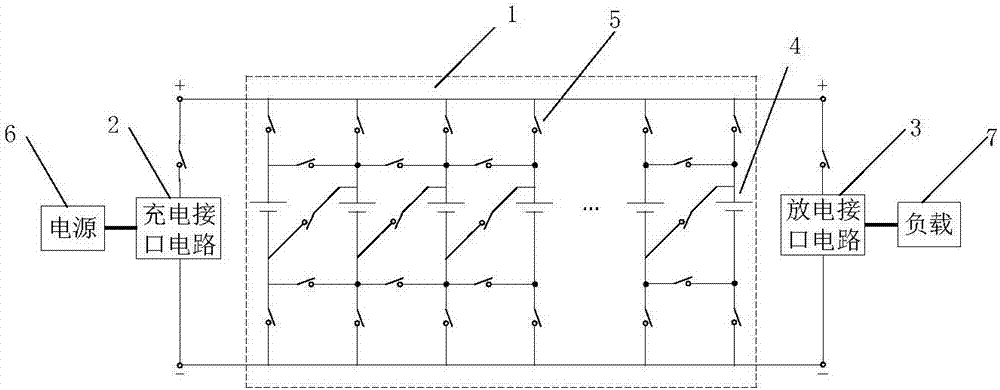
[0003] Traditionally, the battery energy storage system connects battery cells in series and parallel in a fixed way to expand the energy storage capacity and power of the energy storage system. This has two disadvantages: (1) The energy storage system has a short board effect, which makes it difficult to fully Utilizes the energy storage capacity of all battery cells
For example, the charge and discharge ampere hours of a battery pack composed of multiple battery cells connected in series are equal to the battery cell with the least ampere hour, so the energy storage capacity of the battery cell with a larger ampere hour is not fully utilized
(2) There is an unbalanced effect in the energy storage system, which leads to significant differences in the aging degree and speed of the battery cells, shortening the overall life of the energy storage system
The difference in parameters will l

Method used


Image

  • Dynamically-reconfigurable battery energy storage system and method
  • Dynamically-reconfigurable battery energy storage system and method
  • Dynamically-reconfigurable battery energy storage system and method

Examples


Example Embodiment

[0045] Below in conjunction with accompanying drawing and embodiment the present invention will be further described:

[0046] It should be pointed out that the following detailed description is exemplary and intended to provide further explanation to the present application. Unless defined otherwise, all technical and scientific terms used herein have the same meaning as commonly understood by one of ordinary skill in the art to which this application belongs.

[0047]It should be noted that the terminology used here is only for describing specific implementations, and is not intended to limit the exemplary implementations according to the present application. As used herein, unless the context clearly dictates otherwise, the singular is intended to include the plural, and it should also be understood that when the terms "comprising" and / or "comprising" are used in this specification, they mean There are features, steps, operations, means, components and / or combinations ther...


PUM


Abstract

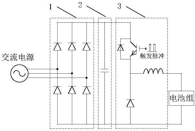
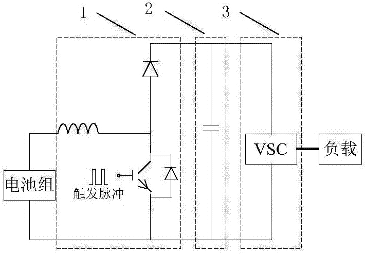
The invention relates to a dynamically-reconfigurable battery energy storage system and method. The system comprises an energy storage system main circuit and a battery management system. The energy storage system main circuit has a charging and discharging interface circuit and an energy storage battery pack connected with the charging and discharging interface circuit. The energy storage battery pack is formed by connecting a plurality of single batteries in parallel. Each single battery is provided with a controllable switch Sn(n=1, 2,..., n) at the two ends thereof. In the energy storage battery pack formed by connecting the plurality of single batteries in parallel, the positive electrode end of each single battery is connected with the positive electrode end of an adjacent single battery through a controllable switch S'n (n = 1, 2,..., n), and the negative electrode end of each single battery is connected with the negative electrode end of the adjacent single battery through a controllable switch S "n (n = 1, 2,..., n). The battery management system is connected with the energy storage system main circuit, and is used for generating an energy storage battery pack reconfiguration decision according to electrical information of the single batteries and a power switching instruction, and controlling connection or disconnection of the controllable switch Sn, the controllable switch S'n and the controllable switch S"n to change topology of the energy storage battery pack.

Description

technical field [0001] The invention belongs to the field of construction and control of battery energy storage systems, in particular to a dynamically reconfigurable battery energy storage system and method. Background technique [0002] With the gradual depletion of fossil energy and the increasing concern of human beings on environmental issues, clean and renewable energy power generation is rapidly expanding, and a new round of energy transformation is gradually advancing. However, renewable energy has inherent characteristics of volatility and randomness, which pose many challenges to the safe, stable, and economical operation of the power grid. Energy storage technology is an effective means to deal with the above challenges, and building a large-scale economical energy storage system is a significant research topic. In addition to pumped storage, battery energy storage is the energy storage technology with the most promising engineering application prospects at this ...

Claims


Application Information

Patent Timeline
IPC IPC(8): H02J7/00
CPCH02J7/0016
Inventor 王飞崔伟谷鸣李伟胡俊鹏张恒旭施啸寒范英乐
Owner STATE GRID SHANDONG ELECTRIC POWER
Why Eureka
Try Eureka