A rotational speed control device

A technology for controlling device and rotating speed, applied in electromechanical devices, controlling mechanical energy, structural connections, etc., can solve the problems of unreliable speed detection accuracy and effect, troublesome device installation, etc., achieve novel structure, improve centrifugal force, and ensure reliability Effect

Active Publication Date: 2019-04-02
QUZHOU UNIV
View PDF3 Cites 0 Cited by
  • Summary
  • Abstract
  • Description
  • Claims
  • Application Information

AI Technical Summary

Problems solved by technology

Although there are devices such as encoders and optical measurement to detect and control the speed, these devices are generally troublesome to install, and they are not suitable for use in harsh environments. The current simple magnetoelectric speed sensor Although it is widely used in automobiles and other fields, the detection accuracy and effect of rotational speed are not very reliable.

Method used


Image

  • A rotational speed control device
  • A rotational speed control device
  • A rotational speed control device

Examples


Embodiment Construction

[0020] The present invention will be described in detail below in conjunction with the accompanying drawings. However, it should be understood that the accompanying drawings are provided only for better understanding of the present invention, and they should not be construed as limiting the present invention.

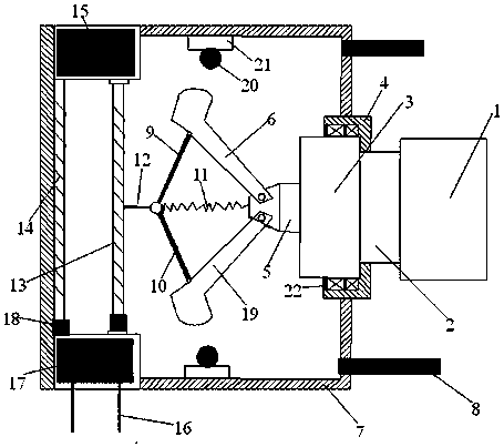
[0021] Such as Figure 1-3 As shown, a rotation speed control device is characterized in that it includes a connecting assembly connected to the rotating shaft to be controlled, a centrifugal assembly, a connecting rod assembly and an electromagnetic induction assembly, wherein the centrifugal assembly is arranged on the connecting assembly, the connecting rod assembly is connected to the centrifugal assembly, the connecting rod assembly is connected to the dynamic induction magnetic coil of the electromagnetic induction assembly, and the The dynamic induction magnetic coil 13 and the fixed induction magnetic coil 14 of the electromagnetic induction assembly constitute...


PUM


Abstract

The invention provides a rotary speed control apparatus. A centrifuging assembly is arranged on a connecting assembly; a connecting rod assembly is connected with the centrifuging assembly; the connecting rod assembly is connected with a dynamic inductive magnetic coil of an electromagnetic induction assembly; the dynamic inductive magnetic coil and a fixed inductive magnetic coil of the electromagnetic induction assembly form an inductive magnetic coil; the fixed inductive magnetic coil is connected with a power supply; and the dynamic inductive magnetic coil is connected with a signal processor. The rotary speed control apparatus provided by the invention adopts mechanical structural design, so that speed detection and control reliability is ensured; centrifuging force of a centrifuging claw is utilized and the centrifuging force is amplified through the connecting rod assembly and is converted into electromagnetic induction; rotary speed detection and control is realized through the distance of the two magnetic inductive coils in electromagnetic induction; the centrifuging claw disclosed in the invention adopts a hollow structure, and a high-density sphere at the centrifuging end is adopted in an auxiliary manner, so that centrifuging force embodiment in high-speed change can be improved; and in addition, the rotary speed control apparatus is creative and reasonable in structure and particularly suitable for rotary speed detection and control in severe environments.

Description

technical field [0001] The invention relates to the technical field of mechanical design and mechanical detection control, in particular to a rotation speed control device, which belongs to the technical field of mechanical design and automation. Background technique [0002] In the mechanical field, for the rotating shaft, the motor is generally used to drive the rotation. During the rotation process, the speed needs to be detected and controlled to prevent excessive speed or overload. Although there are devices such as encoders and optical measurement to detect and control the speed, these devices are generally troublesome to install, and they are not suitable for use in harsh environments. The current simple magnetoelectric speed sensor Although it is widely used in automobiles and other fields, the detection accuracy and effect of rotational speed are not very reliable. [0003] Based on the above technical problems, the present invention provides a rotation speed contr...

Claims


Application Information

Patent Timeline
Patent Type & Authority Patents(China)
IPC IPC(8): H02K7/10H02K11/21
CPCH02K7/10H02K11/21
Inventor 黄斌王角凤
Owner QUZHOU UNIV
Why Eureka
Try Eureka