A high-sensitivity smoke alarm, system and method

A smoke alarm and high-sensitivity technology, applied to alarms, fire alarms, instruments, etc., can solve the problems of high false alarm rate of smoke alarms, achieve the effects of preventing false alarms, eliminating interference, and improving accuracy

Active Publication Date: 2021-04-30
SHANDONG UNIV QILU HOSPITAL
View PDF2 Cites 0 Cited by
  • Summary
  • Abstract
  • Description
  • Claims
  • Application Information

AI Technical Summary

Problems solved by technology

[0005] In order to solve the deficiencies of the prior art, the present disclosure provides a high-sensitivity smoke alarm, system and method, which effectively realizes double detection of black smoke and white smoke, and solves the problem of high false alarm rate of current smoke alarms , to better realize the precise detection and alarm of smoke

Method used


Image

  • A high-sensitivity smoke alarm, system and method
  • A high-sensitivity smoke alarm, system and method
  • A high-sensitivity smoke alarm, system and method

Examples


Embodiment 1

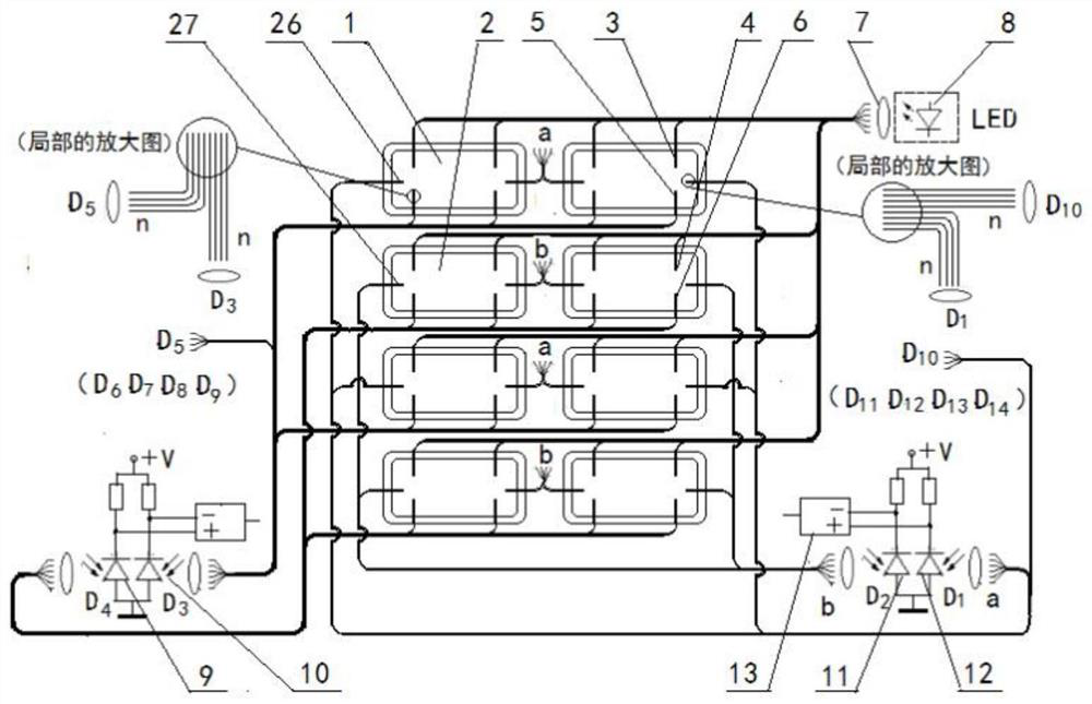
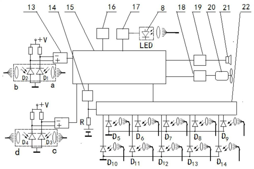
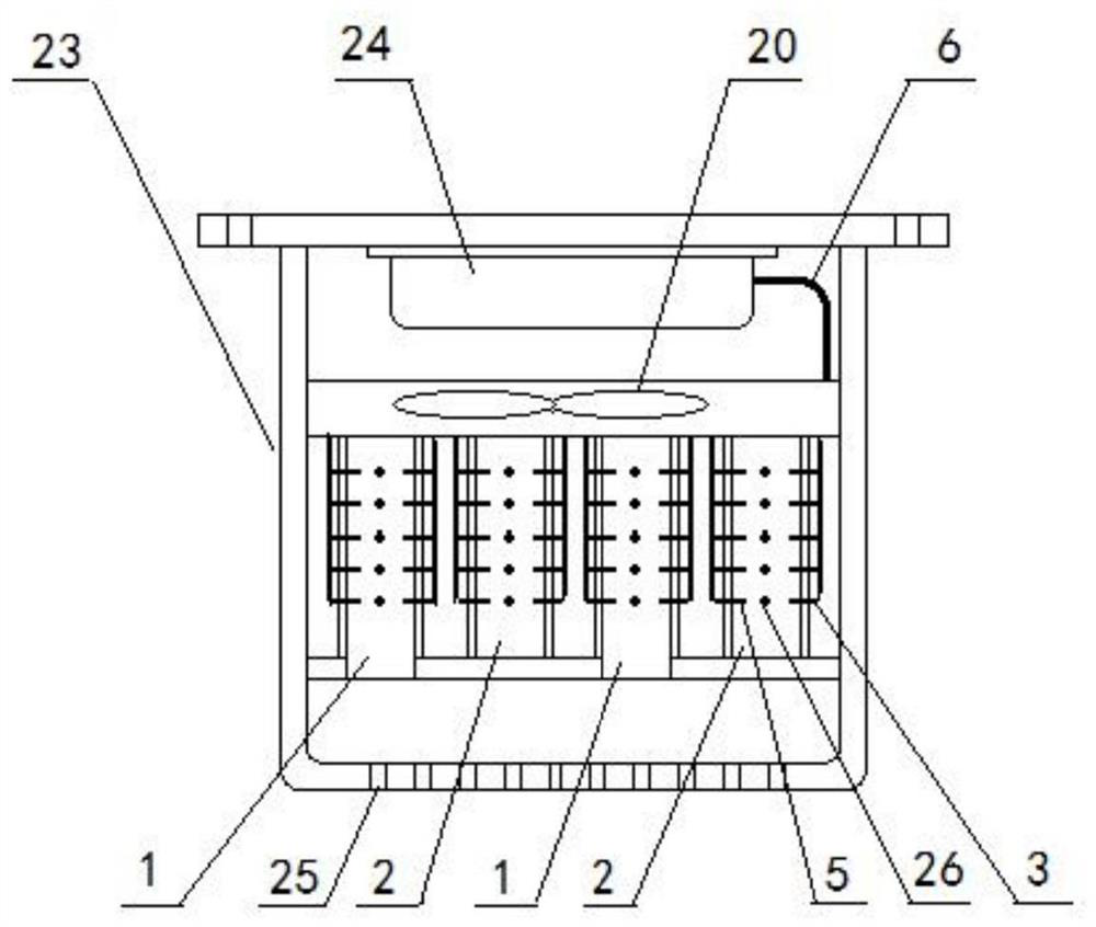
[0048] Such as Figure 1-3 As shown, Embodiment 1 of the present disclosure provides a high-sensitivity smoke alarm, including a housing 23, a light source, a transmitting optical fiber, a receiving optical fiber, four smoke detection cavities 1 and four reference cavities 2, a first detection photodiode 10. The first reference photodiode 9 and the microcontroller 15, the bottom of the housing 23 has a plurality of ventilation holes 25, the bottom of the smoke detection chamber 1 has an air inlet, and the reference chamber 2 is connected with the detection chamber. Compared with the smoke chamber 1, there is no air inlet, and other settings are the same as the smoke detection chamber 1. The reference chamber 2 is used as a reference for the smoke detection chamber 1 to eliminate external interference; the top of the housing 23 is fixed A shielding box 24 is provided for placing the light source and the microcontroller 15; the incident end of the emitting fiber is arranged oppo...

Embodiment 2

[0068] Embodiment 2 of the present disclosure provides a smoke alarm system, including a plurality of smoke alarms described in Embodiment 1 of the present disclosure, and the plurality of smoke alarms share the same light source.

Embodiment 3

[0070] Such as Figure 4 As shown, Embodiment 3 of the present disclosure provides a smoke alarm method, using the smoke alarm described in Embodiment 1 of the present disclosure, the steps are as follows:

[0071] (1) Arrange the smoke alarm at the position where it needs to be arranged, initialize various parameters of the smoke alarm, and turn on the light source;

[0072] (2) The smoke detection cavity monitors the smoke signal in real time. When the smoke signal is detected, it is compared with the signal of the reference cavity to determine whether it is an error signal caused by external environmental interference;

[0073] (3) If the smoke signal of the smoke detection chamber is close to or the same as the signal of the reference chamber, go to step (5);

[0074] (4) If there is a large difference between the smoke signal of the smoke detection chamber and the signal of the reference chamber, it is judged to be a smoke signal and an alarm is given;

[0075] (5) Judg...


PUM


Abstract

The present disclosure provides a high-sensitivity smoke alarm, a system and a method, including a housing, a light source, a transmitting optical fiber, a receiving optical fiber, at least one smoke detection chamber and at least one reference chamber, a first inspection photodiode, a first reference Photodiodes and microcontrollers, by setting the smoke detection cavity and the reference cavity, and comparing the signals of the smoke detection cavity and the reference cavity during smoke detection, effectively overcome the false alarm of the smoke alarm caused by environmental factors such as temperature changes , by setting up multi-layer smoke detection layers, each layer is equipped with a smoke detection chamber and a reference chamber, and by detecting the smoke detection signal in each layer of smoke detection chambers, the layered detection of smoke is realized to prevent dust and other environmental factors from causing Only a certain layer or a few layers detect false alarms caused by "false smoke signals", thereby further improving the accuracy of smoke detection.

Description

technical field [0001] The present disclosure relates to the technical field of smoke alarms, in particular to a high-sensitivity smoke alarm, a system and a method. Background technique [0002] The statements in this section merely provide background information related to the present disclosure and may not necessarily constitute prior art. [0003] Ordinary photoelectric smoke alarms are divided into two types: shading type and scattering type, which are developed by utilizing the characteristic that the smoke generated during a fire can change the light intensity. Patent No. CN102622848B introduces a through-beam point-type optical fiber smoke detector, and patent No. CN102622847B introduces a reflective point-type optical fiber smoke detector. And receiving optical fiber for smoke detection, which reduces the cost of smoke detectors and eliminates the aging defects caused by electronic components. [0004] However, the inventors of the present disclosure have found in...

Claims


Application Information

Patent Timeline
Patent Type & Authority Patents(China)
IPC IPC(8): G08B17/103G08B17/107
CPCG08B17/103G08B17/107
Inventor 赵明
Owner SHANDONG UNIV QILU HOSPITAL
Why Eureka
Try Eureka