

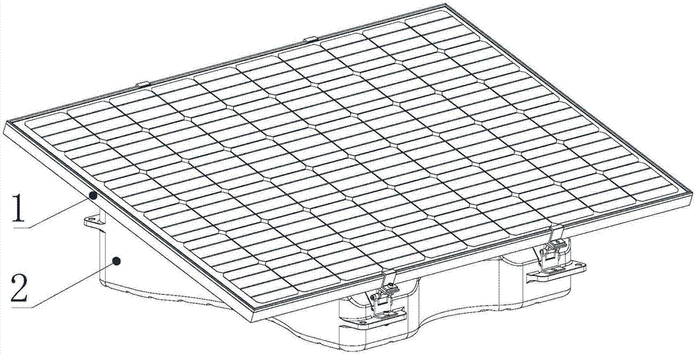
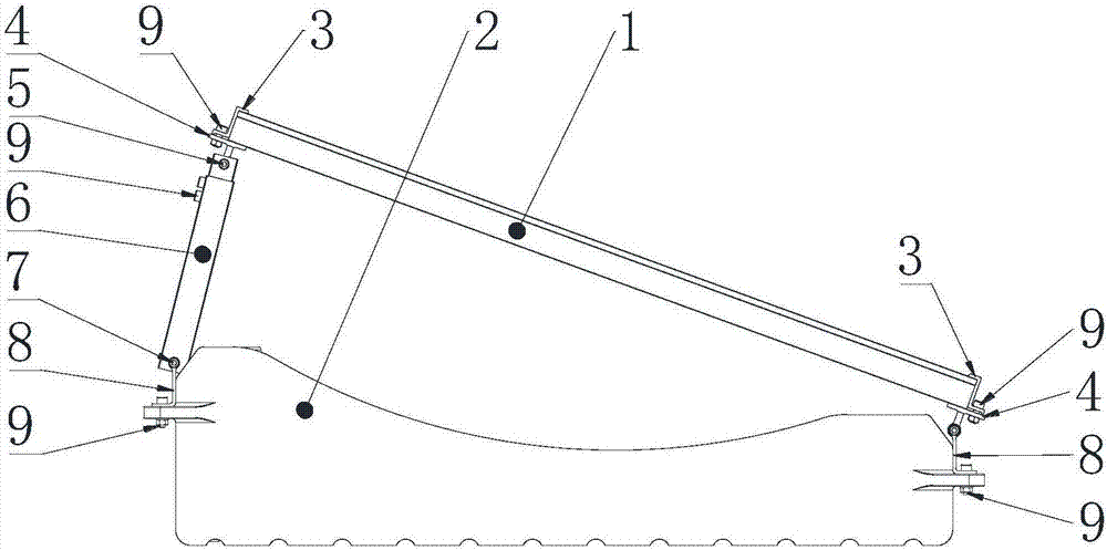
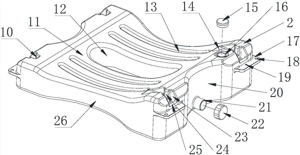
Integrated photovoltaic support system
A photovoltaic bracket and integrated technology, which is applied in the support structure of photovoltaic modules, photovoltaic power generation, photovoltaic modules, etc., can solve the problems of unadjustable photovoltaic panel angle, reduce production costs, and cannot be filled with liquid counterweights, etc., to achieve environmental benefits The effect of protection, large selection range and low production management cost
- Summary
- Abstract
- Description
- Claims
- Application Information
AI Technical Summary
Problems solved by technology
Method used
Image

Examples
Embodiment Construction
[0037]In describing the present invention, it is to be understood that the terms "center", "longitudinal", "transverse", "front", "rear", "left", "right", "top", "bottom" etc. indicate The orientation or positional relationship is based on the orientation or positional relationship shown in the drawings, and is only for the convenience of describing the present invention and simplifying the description, rather than indicating or implying that the referred device or element must have a specific orientation or be configured in a specific orientation. and operation, and therefore should not be construed as limiting the invention. In addition, the terms "first" and "second" are used for descriptive purposes only, and cannot be interpreted as indicating or implying relative importance or implicitly specifying the quantity of indicated technical features. Thus, a feature defined as "first" and "second" may explicitly or implicitly include one or more of these features. In the descr...
PUM
 Abstract
Description
Claims
Application Information