
Annular load box for self-balance method

A load box and self-balancing technology, which is used in construction, infrastructure testing, infrastructure engineering, etc., can solve the problems of unstable grouting effect, small effective area of ​​oil cylinder, and large grouting space.

Inactive Publication Date: 2017-09-19
ZHEJIANG OUGAN MASCH CO LTD
View PDF5 Cites 0 Cited by
  • Summary
  • Abstract
  • Description
  • Claims
  • Application Information

AI Technical Summary

Problems solved by technology

However, in this technical solution, there are still defects: 1. The effective area of ​​the oil cylinder is small, and the working pressure of the load box is high under the same bearing capacity. When the pressure of the contact surface is greater than or close to the concrete strength at that time, it is easy to cause the contact surface The concrete is broken, resulting in false displacement; 2. The overall height of the technical solution is high, and the grouting space is large after the inspection is completed, and the grouting effect is unstable

Method used


Image

  • Annular load box for self-balance method
  • Annular load box for self-balance method
  • Annular load box for self-balance method

Examples


Embodiment Construction

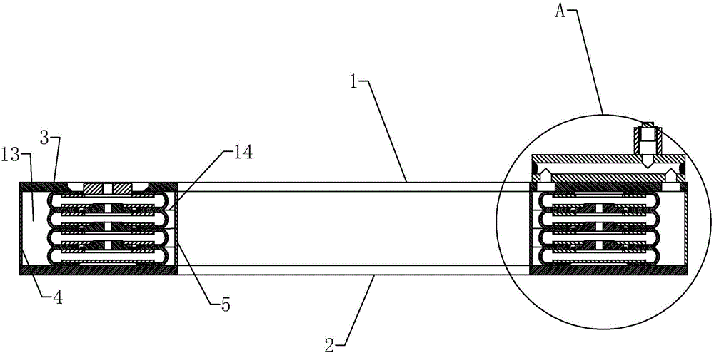
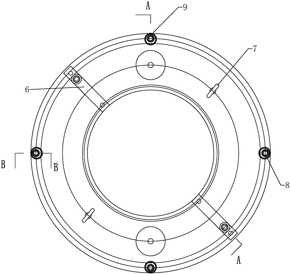
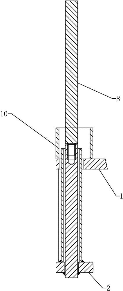
[0024] pass Figure 1 to Figure 4 The self-balancing method of the present invention is further described with an annular load box.

[0025] An annular load box for self-balancing method, comprising an upper annular steel plate 1 , a lower annular steel plate 2 , an outer annular baffle 4 , an inner annular baffle 5 and a pressure device 3 . The upper annular steel plate 1 and the lower annular steel plate 2 are set opposite to each other up and down, and a central hole is opened at the central position for the grouting pipe 11 to pass through. The outer annular baffle plate 4 is connected to the outer edge position of the upper annular steel plate 1 and the lower annular steel plate 2, and the inner annular baffle plate 5 is connected to the inner edge position of the upper annular steel plate 1 and the lower annular steel plate 2, that is, the central hole position, It should be noted here that the upper end of the outer annular baffle 4, the upper end of the inner annular ...


PUM


Abstract

The invention discloses an annular load box for a self-balance method. The annular load box comprises an upper annular steel plate, a lower annular steel plate, an outer ring baffle, an inner ring baffle and a pressure device. The pressure device comprises a plurality of annular oil cavity expansion units which are overlapped in an up-and-down mode and communicate with one another, the annular oil cavity expansion unit located at the uppermost position is connected with the upper annular steel plate and can be connected with a hydraulic loading device, and the annular oil cavity expansion unit located at the lowermost position is connected with the lower annular steel plate; an outer annular filling cavity is formed among the upper annular steel plate, the lower annular steel plate, the outer ring baffle and the pressure device, and an inner annular filling cavity is formed among the upper annular steel plate, the lower annular steel plate, the inner ring baffle and the pressure device; the load box is further provided with a grouting valve block, the grouting valve block is provided with a grouting opening, a pipe cavity, a first grout outlet and a second grout outlet, the grouting opening, the pipe cavity, the first grout outlet and the second grout outlet are mutually conductive, and the first grout outlet and the second grout outlet communicate with the outer annular filling cavity and the inner annular filling cavity separately. The annular load box has the advantages that cost is saved, and meanwhile detection stability is guaranteed.

Description

technical field [0001] The invention relates to a ring-shaped load box for a self-balancing method. Background technique [0002] Self-balancing test technology is a new type of test technology for foundation bearing capacity that has been rapidly developed and promoted at home and abroad in recent years. It can effectively solve problems that are difficult to solve by traditional test methods, such as test piles on water, test piles on narrow and long sites, and large-diameter deep and long grouting. Pile bearing capacity testing and other engineering technical problems, and is favored by the engineering community for its time-saving, economical, and technologically advanced advantages. Different from the stacking method and the anchor pile method, the self-balancing method sets the loading device at the bottom or middle and lower parts of the foundation, so that the upper and lower parts of the foundation act as a counter force system, so that it is not limited by the site...

Claims


Application Information

Patent Timeline
IPC IPC(8): E02D33/00
CPCE02D33/00
Inventor 毛宇靖
Owner ZHEJIANG OUGAN MASCH CO LTD
Learn More