Tile water immersing device for building
A technology for construction and ceramic tiles, applied in construction, unloading devices, building structures, etc., can solve problems such as shedding, cracks, slow operation process, etc., and achieve the effect of improving absorption efficiency and water absorption uniformity
- Summary
- Abstract
- Description
- Claims
- Application Information
AI Technical Summary
Problems solved by technology
Method used
Image

Examples
Embodiment Construction
[0020] The present invention will be described in detail below in conjunction with the accompanying drawings.
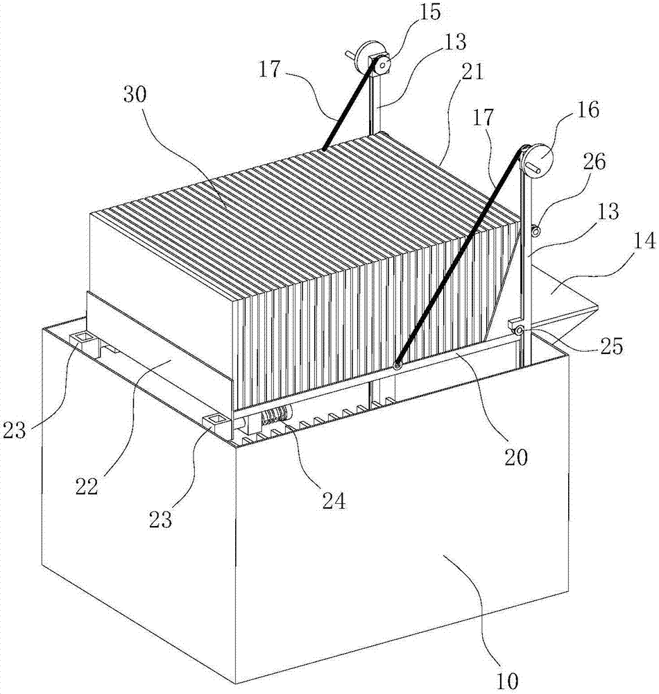
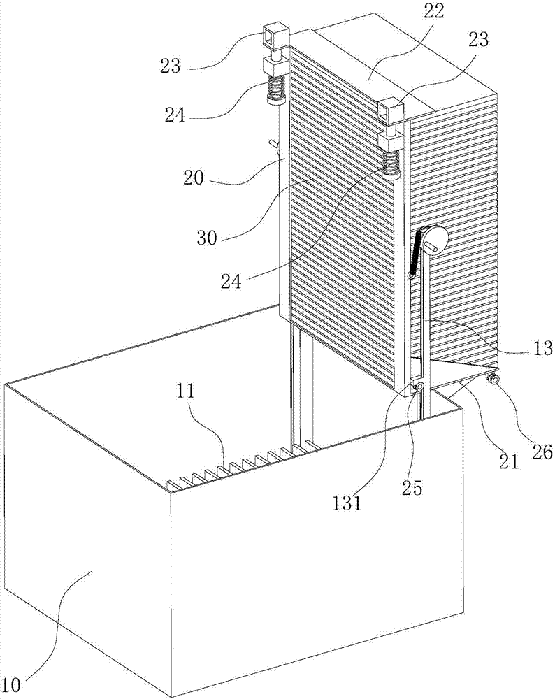
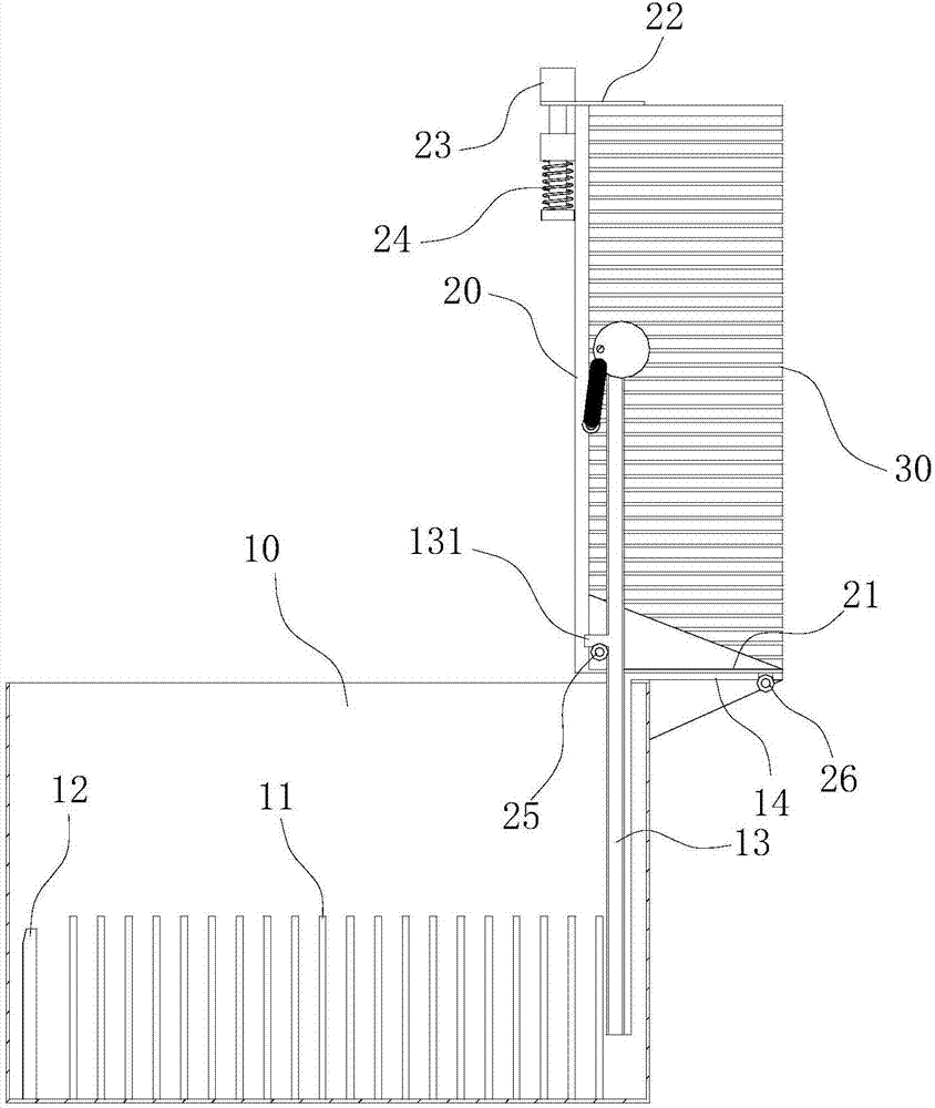
[0021] Such as Figure 1-6 As shown, a ceramic tile immersion device for construction includes a pool 10, and a lifting platform 20 reciprocatingly arranged in the pool 10 along the vertical direction, the lifting platform 20 is used to carry ceramic tiles 30, and the lifting platform 20 During the reciprocating movement in the vertical direction, the tiles 30 can be completely submerged below the water surface of the pool 10 , and the tiles 30 can also be moved upwards until they are completely separated from the water surface. Further, the device also includes a separation mechanism for separating two adjacent tiles 30; Hollow part, the bottom of the pool 10 is provided with a protruding part 11 protruding upwards in the vertical direction, the dimension of the protruding part 11 along the thickness direction of the ceramic tile 30 is smaller than the thickness of...
PUM
 Abstract
Description
Claims
Application Information
PatSnap Eureka turns technology decisions into work you can execute. Powered by our Innovation Knowledge Graph, it runs expert workflows across engineering, life sciences, materials and intellectual property. Get your review-ready output in minutes.


