
Axial Flow Compressor Airfoil Design Method and Axial Flow Compressor Airfoil

A technology of an axial flow compressor and a design method, which is applied in the field of axial flow compressor blade profile design and axial flow compressor blade profile, can solve the problem that it is difficult to design the optimal relative position of the maximum relative thickness, and it is difficult to flexibly adjust the maximum blade profile. The relative position of the relative thickness, etc., to achieve the effect of increasing the design space of the blade, increasing flexibility, and continuous surface curvature

Active Publication Date: 2019-09-24
SHANGHAI ELECTRIC GAS TURBINE CO LTD
View PDF6 Cites 2 Cited by
  • Summary
  • Abstract
  • Description
  • Claims
  • Application Information

AI Technical Summary

Problems solved by technology

[0005] In addition, the relative position of the maximum relative thickness of the axial flow compressor airfoil is an important parameter affecting the aerodynamic characteristics of the airfoil. The design method in the prior art is difficult to flexibly adjust the relative position of the maximum relative thickness of the airfoil. Therefore, it is difficult to design the maximum relative Best Relative Position for Thickness

Method used


Image

  • Axial Flow Compressor Airfoil Design Method and Axial Flow Compressor Airfoil
  • Axial Flow Compressor Airfoil Design Method and Axial Flow Compressor Airfoil
  • Axial Flow Compressor Airfoil Design Method and Axial Flow Compressor Airfoil

Examples


Embodiment Construction

[0048] The implementation of the present invention will be illustrated by specific specific examples below, and those skilled in the art can easily understand other advantages and effects of the present invention from the contents disclosed in this specification.

[0049] It should be noted that the structures, proportions, sizes, etc. shown in the drawings attached to this specification are only used to match the content disclosed in the specification, for those who are familiar with this technology to understand and read, and are not used to limit the implementation of the present invention. Limiting conditions, so there is no technical substantive meaning, any modification of structure, change of proportional relationship or adjustment of size, without affecting the effect and purpose of the present invention, should still fall within the scope of the present invention. within the scope covered by the disclosed technical content. At the same time, terms such as "upper", "lo...


PUM


Abstract

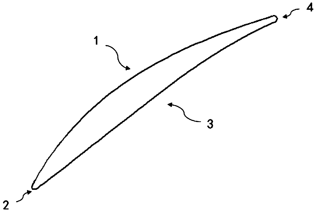
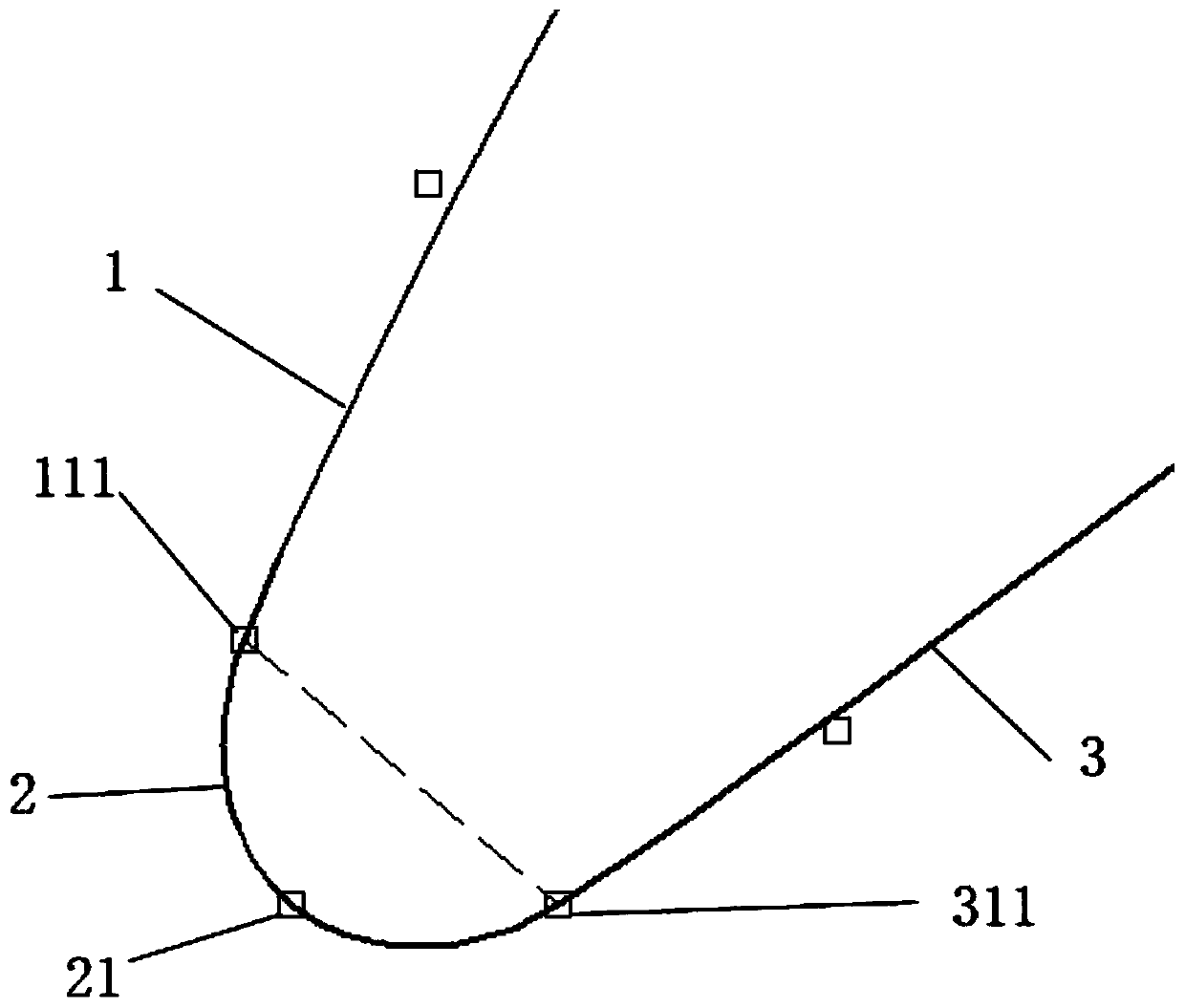
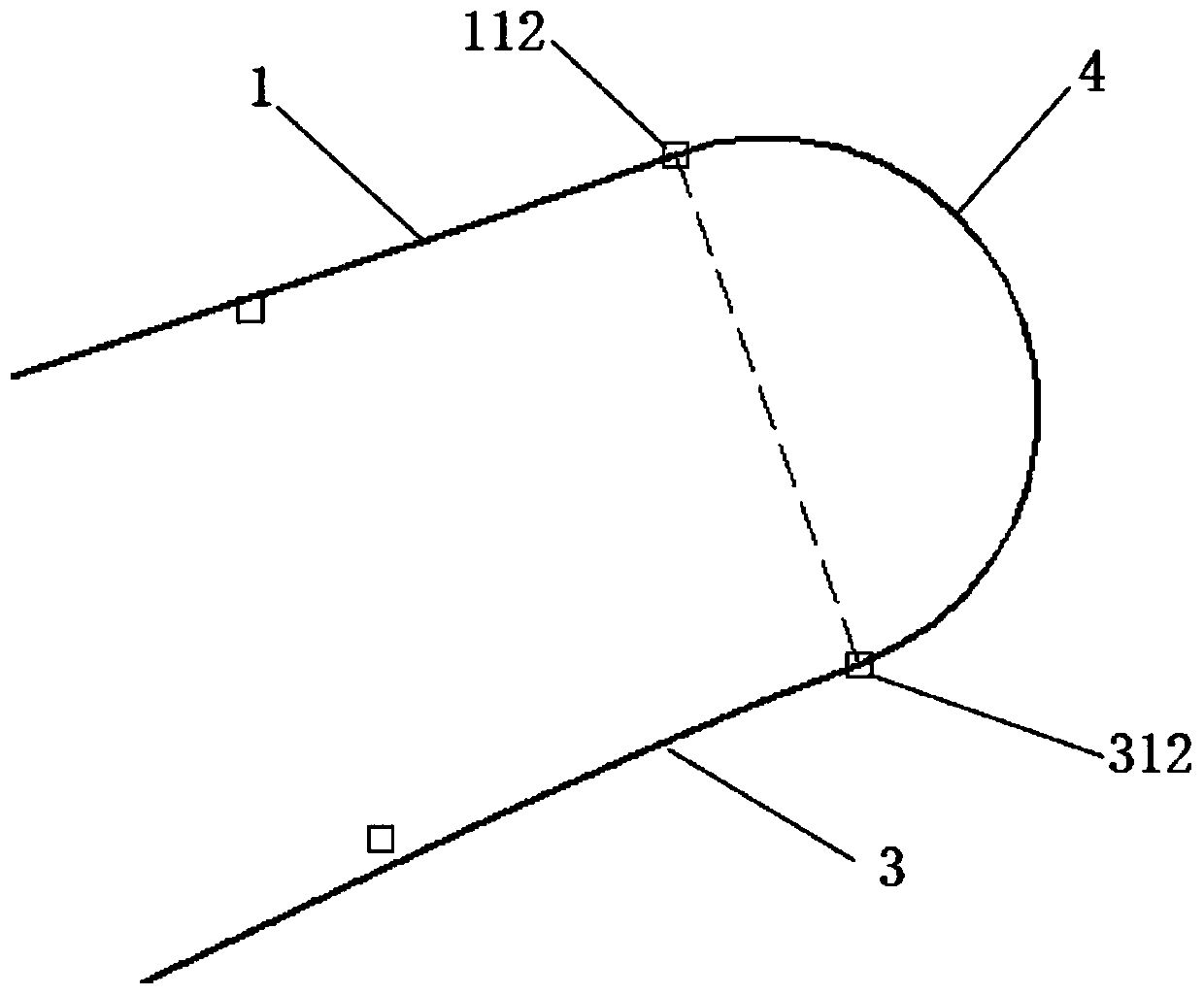
The invention provides a design method of an axial flow gas compressor blade and the axial flow gas compressor blade. The design method of the axial flow gas compressor blade comprises the steps of designing the front edge of the blade and the tail edge of the blade; designing the force suction face of the blade; designing the pressure face of the blade; ensuring first-order derivative continuity of the connecting points, wherein the connecting points comprise the connecting point of the front edge and the force suction face, the connecting point of the front edge and the pressure face, the connecting point of the force suction face and the tail edge, and the connecting point of the pressure face and the tail edge. According to the design method of the axial flow gas compressor blade, the blade with the front edge in a round or oval shape can be precisely designed, local modification of the blade can be achieved, design space of the blade can be further increased, the blade design flexibility is increased, and the designed blade is continuous in surface curvature. Through the method, an existing blade is fitted, the rule of the control points can be analyzed, and the geometric database can be built.

Description

technical field [0001] The invention relates to the technical field of axial flow compressors, in particular to an axial flow compressor blade profile design method and an axial flow compressor blade profile. Background technique [0002] In the prior art, the design method of the blade profile of the axial flow compressor has a design method of superimposed arc and thickness distribution. Many classic airfoils, such as the NACA65 airfoil in the United States, the C4 airfoil in the United Kingdom, and the BC6 airfoil in the former Soviet Union, are all designed with the design method of arc superimposed thickness distribution. [0003] In the prior art, it is also possible to modify the profile lines of the leading edge suction side and the leading edge pressure side based on the existing airfoil and perform fitting for the suction side and pressure side profile lines. [0004] The surface curvature of the airfoil of the axial flow compressor designed by the design method i...

Claims


Application Information

Patent Timeline
Patent Type & Authority Patents(China)
IPC IPC(8): F04D29/38
Inventor 俞松林
Owner SHANGHAI ELECTRIC GAS TURBINE CO LTD
Learn More