Valve insert for heater valve and heater having heater valve

A technology of heating body and heating element, which is applied in the direction of household heating, heating method, household appliances, etc., can solve problems such as collision

Inactive Publication Date: 2017-09-19
OVENTROP GMBKH & KO
View PDF4 Cites 1 Cited by
  • Summary
  • Abstract
  • Description
  • Claims
  • Application Information

AI Technical Summary

Problems solved by technology

[0005] All solutions known from the prior art therefore have the disadvantage that the flow emanating from the heating body valve or from the valve insert formed in it is directed into the heating element or is fixed Predetermined, either only p

Method used


Image

  • Valve insert for heater valve and heater having heater valve
  • Valve insert for heater valve and heater having heater valve
  • Valve insert for heater valve and heater having heater valve

Examples


Embodiment Construction

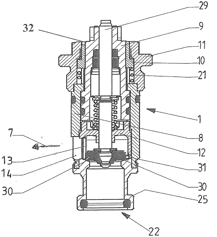
[0039] exist figure 1 A heating body 3 with a heating body valve 2 and a valve insert 1 is shown in .

[0040] The heating body 3 has two heating elements 4 , 5 arranged parallel to one another. These are preferably constructed in the form of plates, wherein the inner chambers of the heating elements 4 , 5 can be passed through by a heating medium. The heating elements 4, 5 are connected by tube blocks 23, 24 crossing each other. First tube blocks 23 coaxial with one another open into the heating elements 4 , 5 . A coaxial second pipe piece 24 accommodates the valve insert 1 . The second tube block 24 is in figure 1 The upper end of the center accommodates the first end 25 of the valve insert 1 . A heating medium feed 26 is adjoined sealingly to this first end 25 of the valve insert 1 . The other end of the second pipe block 24 is completely penetrated by the second end of the valve insert 1 and is threaded on the junction side of the pipe block 24 with the head block 11...


PUM


Abstract

The invention relates to a valve insert (1) for a heater valve (2). The valve insert is used for controlling the flow rate of a heating medium and/or regulating the flow rate of the heating medium; the valve insert has a presetting device (9) by means of which the flow rate can be throttled to a predetermined value, and is positioned in the heater valve through an inflow and outflow openings (14, 22) in such a way that the flow rate supplied to a heater (3) is allocated to at least two heating elements in any ratio, and/or optionally, the flow rate is directed into one or the other heating element of the heating elements; a device for setting the flow direction of the flow rate is integrated in the valve insert, the device can be externally accessible and actuated, and the device can directly change the flow direction of the flow rate from the valve insert.

Description

technical field [0001] The invention relates to a valve insert for a heating body valve, which is independent of the differential pressure acting across the heating body valve, for controlling the flow rate of a heating medium and / or for regulating the flow rate of a heating medium, so that The valve insert has a presetting device, which controls the flow rate to a value to be specified, and the valve insert is positioned with its inflow and outflow openings in the heater valve in such a way : such that the flow supplied to the heating body is distributed in arbitrary proportions to at least two heating elements of the heating body, and / or optionally, the flow flows directionally into the heating elements in one or the other heating element. Background technique [0002] Valve inserts for heating body valves are known in the prior art with the features described above. Thus, DE 10 2007 016 960 shows, for example, a valve insert for controlling the throughflow, which, with ...

Claims


Application Information

Patent Timeline
IPC IPC(8): F16K1/52F16K11/085F24D19/10F16K17/30
CPCF16K1/526F16K11/085F16K17/30F24D19/1015F24D19/0073F24D19/1018F24D2220/0257F24D2220/2054F16K1/52
Inventor R.施皮克曼D.旺德林
Owner OVENTROP GMBKH & KO
Why Eureka
Try Eureka