
electrical connector

A technology of electrical connectors and connectors, which is applied in the direction of connection, components of connection devices, circuits, etc., can solve the problem of lack of moving locking rings, etc., achieve overall axial volume reduction, axial length reduction, avoid The effect of the use of the entrance bevel

Active Publication Date: 2020-07-24
STAUBLI FAVERGES SA
View PDF3 Cites 0 Cited by
  • Summary
  • Abstract
  • Description
  • Claims
  • Application Information

AI Technical Summary

Problems solved by technology

[0003] A problem arising comparing the devices known from DE-A-19645730 and US-A-4547,032 is that the device lacks a locking ring movable between a forward position and a rearward position

Method used


Image

  • electrical connector
  • electrical connector
  • electrical connector

Examples


Embodiment Construction

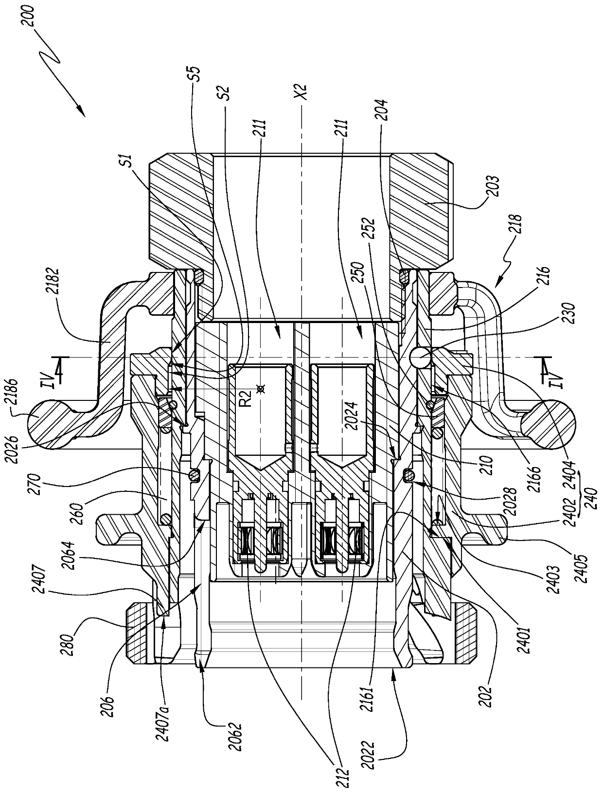
[0037]In the remainder of the description, the forward direction of the connector element is defined as the direction oriented in the fitting or coupling direction, ie towards the complementary connector element. In contrast, a rearward direction of a connector element is defined as being opposite to a complementary connector element.

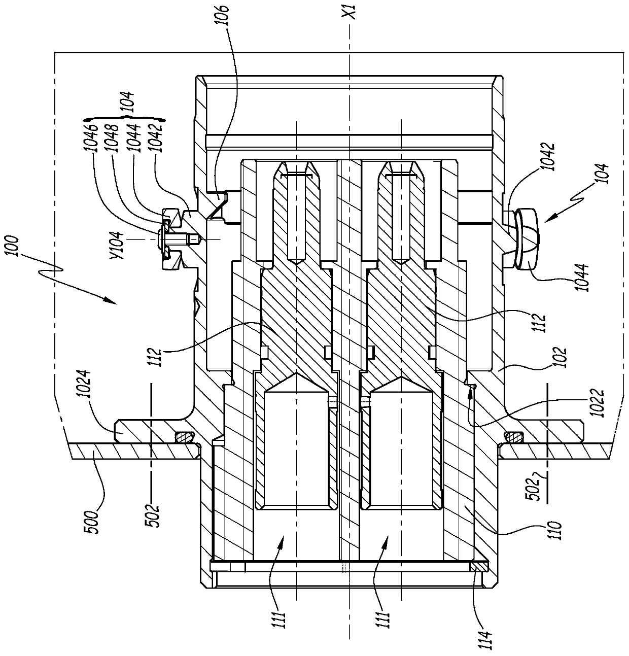
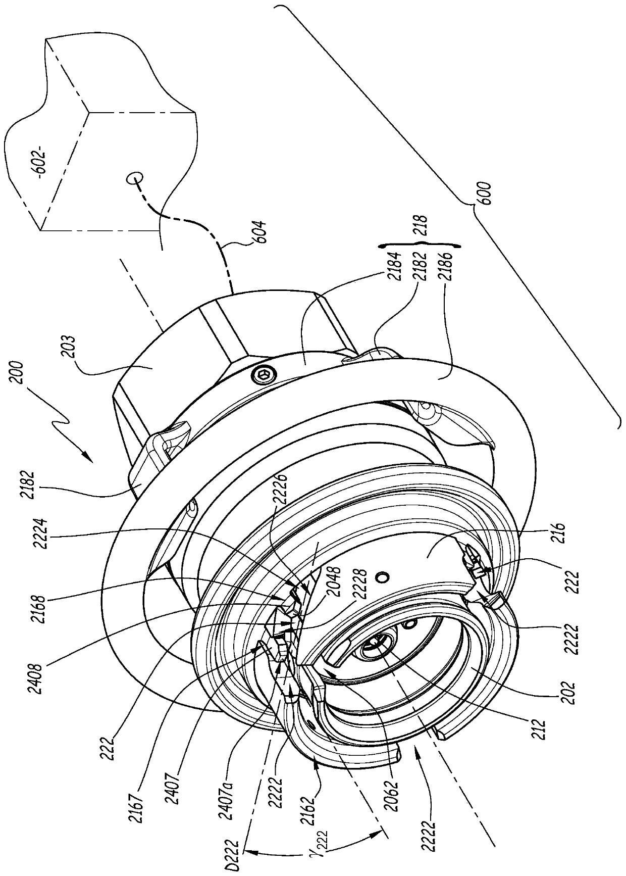
[0038] like figure 1 The female element 100 shown in the decoupled state belongs to Figure 5 The electrical connector R shown in, and hereinafter the electrical connector R is also included in the Figure 2 to Figure 4 The male element 200 is shown in a decoupled state.

[0039] The female element 100 has an overall cylindrical structure centered on the axis X1. The female element 100 comprises an outer body 102 on which three locking pins 104 are fixedly positioned and directed radially outwards. Each locking pin 104 extends along an axis Y104 radial to the axis X1 and comprises a hub 1042 formed in one piece with a main body 102, a rolle...


PUM


Abstract

A first connector (R) element (100) includes a first body (102) secured to a locking pin (104) and a first indexing member (106). The second connector (R) element (200) includes a locking ring (216) axially fixed and rotatable about the second body (202) and at least one second indexing member. The second connector element (200) includes a blocker (230) that moves relative to the locking ring (216) between a first position preventing rotation of the locking ring (216) and a second release position. The second connector element (200) includes a locking ring (240) that moves relative to the second body (202) between a forward position and at least one retracted position. The blocking member (230) is capable of blocking the locking ring (216) in a configuration in which the slot opening is aligned with the locking pin. During assembly, the latch ring (240) is pushed back by a portion (1044) of the first connector element (100).

Description

technical field [0001] The invention relates to an electrical connector comprising a first connector element and a second connector element complementary to the first connector element, the two connector elements being arranged to cooperate with each other. For example, such connectors may be used to electrically connect an electric vehicle to a power source for charging the vehicle's battery. Background technique [0002] A connector suitable for this application is known from EP-A-2,752,946. In this connector, during assembly or connection of the elements of the connector, their bodies are guided about a longitudinal axis in order to align each plug with the corresponding contact. Next, the pins are secured by engaging in the corresponding locking slots, withdrawing the security tabs and resiliently returning the security tabs to the position of the blocking pins in the slots. In order to allow the pin to pass automatically through the corresponding locking slot, it is n...

Claims


Application Information

Patent Timeline
Patent Type & Authority Patents(China)
IPC IPC(8): H01R13/627H01R13/52H01R13/639H01R13/641
CPCH01R13/5219H01R13/6276H01R13/6278H01R13/639H01R13/641H01R13/625H01R13/631H01R13/633
Inventor A-C·泰伯吉恩C·杜里尤科斯F·米勒
Owner STAUBLI FAVERGES SA
Learn More