Device and method for forming seamless dual-layer spiral coil pipe

A technology of spiral coil and forming device, which is applied to forming tools, heat exchange equipment, metal processing equipment, etc., can solve the problems of complex manufacturing and difficult modification of welding defects, and achieve the effect of difficult repair, simple structure and defect avoidance.

Pending Publication Date: 2017-09-22
JIANGSU NEW HENGJI SPECIAL EQUIP
View PDF5 Cites 2 Cited by
  • Summary
  • Abstract
  • Description
  • Claims
  • Application Information

AI Technical Summary

Problems solved by technology

[0003] The purpose of the present invention is to design a seamless double-layer spiral coil forming device for the problems that the existing double-layer spiral coil tubes need to be wel...

Method used


Image

  • Device and method for forming seamless dual-layer spiral coil pipe
  • Device and method for forming seamless dual-layer spiral coil pipe
  • Device and method for forming seamless dual-layer spiral coil pipe

Examples


Embodiment 1

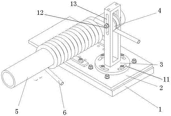
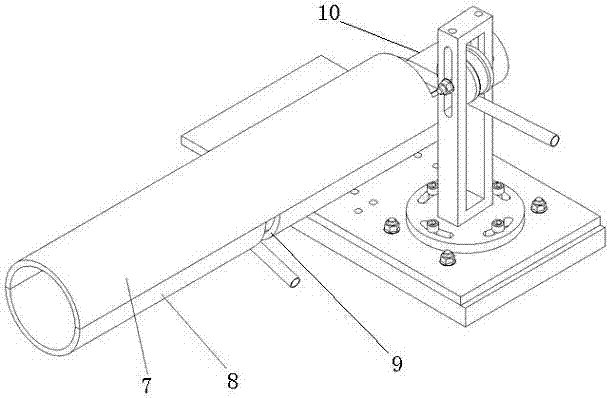
[0025] Such as Figure 2-4 shown.

[0026] A seamless double-layer spiral coil forming device, which mainly includes a lathe middle carriage 1 capable of moving left and right or forward and backward, a base 2, a roller bracket 3, an angle-adjustable roller 4, an inner pipe mold 5, an outer layer The tube upper die 7 and the outer tube lower die 8, the base 2 are fixed on the middle carriage 1 of the lathe through T-shaped slots, and the bottom of the roller bracket 3 is provided with four waist-shaped installation and fixing holes, which can be fixed on the base 2 by bolts And the circumferential adjustment of the position can be realized; the roller 4 is installed on the roller shaft 12, and the roller shaft 12 is fixed in the elongated slot 13 on the column of the roller bracket 3 by a nut, adjusting the position of the roller shaft can realize the adjustment of the height of the roller Adjustment. When the inner layer spiral coil is processed, the left end of the inner l...

Embodiment 2

[0028] Such as Figure 2-4 as shown

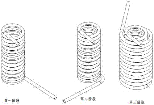
[0029] A seamless double-layer spiral coil forming method, it comprises the following steps:

[0030] First, the original tool holder of the lathe is removed, and the base 2 is fixed on the middle carriage 1 of the lathe through T-slot bolts. The lower part of the roller bracket 3 is designed with 4 waist holes, which can realize its rotation in the vertical direction. Adjust the rotation angle of the roller bracket 3 according to the rising angle of the inner right-handed spiral coil, keep the two consistent, and then tighten it with screws fixed on the base 2. Adjust the height of the roller 4 in the roller bracket 3 so that the straight pipe that penetrates under the roller 4 can be tangent to the upper part of the inner layer pipe mold 5, and then tighten the hexagonal flange nuts at both ends of the central axis of the roller 4. Pass the straight pipe under the roller 4, press the end on the inner pipe mold 5 through the pressing b...


PUM


Abstract

Provided are a device and method for forming a seamless dual-layer spiral coil pipe. The device is characterized by mainly comprising a lathe middle carriage, a base, a roller support, a roller, an inner pipe mold, the coil pipe, an outer pipe upper mold and an outer pipe lower mold. The base is fixed to the lathe middle carriage through T-shaped slotted bolts. The roller support is fixed to the base through screws. The roller is fastened with nuts after being adjusted to have the proper height. The end portion of the inner pipe mold is clamped in a three-claw chuck, and the tail of the inner pipe mold is jacked by a jacking base at the tail of a lathe. When the inner layer of the right-hand spiral coil pipe is formed, the middle carriage is moved rightwards, and when the outer layer of the right-hand spiral coil pipe is formed, the middle carriage is moved leftwards. With the device and method, the seamless dual-layer spiral coil pipe can be formed, the structure is simple, and the forming precision is controllable.

Description

technical field [0001] The invention relates to a spiral coil forming device, in particular to a double-layer spiral coil forming device, in particular to a seamless double-layer spiral coil forming device and method suitable for manufacturing heat exchange tubes in the field of nuclear power. Background technique [0002] At present, the double-layer spiral coil is mostly welded by welding the preformed inner spiral coil and the outer spiral coil, such as figure 1 Shown, still do not have the manufacture method of seamless double-layer spiral coil. Contents of the invention [0003] The purpose of the present invention is to design a seamless double-layer spiral coil forming device for the problems that the existing double-layer spiral coil tubes need to be welded when they are formed, resulting in complicated manufacturing and welding defects that are easy to occur at the welds and are not easy to modify. Provide its production and processing method. [0004] One of te...

Claims


Application Information

Patent Timeline
IPC IPC(8): B21D11/06B21D11/22B21D37/10B21D53/06
CPCB21D11/06B21D11/22B21D37/10B21D53/027B21D53/06
Inventor 廖亭
Owner JIANGSU NEW HENGJI SPECIAL EQUIP
Why Eureka
Try Eureka