Method of designing phase grating pattern providing modified illumination optimum for producing a target pattern and method of manufacturing a photo mask system comprising the phase grating pattern

a phase grating and target pattern technology, applied in the field of photolithographic process, can solve the problems of reducing the resolution of the photolithographic process, so as to achieve the effect of improving the resolution or depth of focus achieved in the photolithographic process

Inactive Publication Date: 2005-06-28
SAMSUNG ELECTRONICS CO LTD
View PDF1 Cites 7 Cited by
  • Summary
  • Abstract
  • Description
  • Claims
  • Application Information

AI Technical Summary

Benefits of technology

[0009]An object of the present invention is to provide a method of designing a phase grating pattern by which the illumination of a primary mask can be modified in order to increase the resolution of a photolithographic process in which the main pattern of the primary mask is transcribed onto a wafer.
[0020]According to the present invention, even though conventional illumination is used as an exposure light source, the light emitted by the light source can be modified to realize practically any form of illumination at the mask level. Thus, the resolution or depth of focus achieved in a photolithographic process can be improved.

Problems solved by technology

The resolution of the photolithographic process may be limited by several factors, such as the wavelength of an exposure light source, the numerical aperture of a projection lens, the depth of focus, the process parameters, and the like.
The need to increase the resolution of the photolithographic process, however, surpasses the limitations of current exposure apparatus.
Such gratings up until now have been limited to simple line-space or simple mosaic types of gratings.
Such grating patterns are basically composed of simple line-space or square mosaic forms of patterns and are thus limited to providing modified illumination corresponding to a simple dipole or quadrupole.
Simple dipole or quadrupole modified illumination can only achieve a limited increase in the resolution of the photolithographic process.
In addition, only one modified form of illumination is practical for each mask in the conventional technique of providing a phase grating pattern.
Thus, although one form of modified illumination may be optimum for use in producing some of the wiring patterns of the semiconductor circuit, the same modified illumination may be not optimum for use in producing other patterns constituting the same circuit.
In other words, the simple form of the modified illumination possible with the prior art cannot be optimum for use in producing all of the patterns of the same semiconductor circuit.
However, these techniques significantly increase the time and cost of carrying out the photolithography process.
In addition, it is difficult to realize a pattern transition corresponding to a desired target pattern even when these additional compensation techniques are performed.

Method used


Image

  • Method of designing phase grating pattern providing modified illumination optimum for producing a target pattern and method of manufacturing a photo mask system comprising the phase grating pattern
  • Method of designing phase grating pattern providing modified illumination optimum for producing a target pattern and method of manufacturing a photo mask system comprising the phase grating pattern
  • Method of designing phase grating pattern providing modified illumination optimum for producing a target pattern and method of manufacturing a photo mask system comprising the phase grating pattern

Examples


Embodiment Construction

[0031]The present invention will be described in detail hereinafter with reference to the attached drawings. In the drawings, the thicknesses of layers or regions are exaggerated for clarity. Also, like reference numerals denote like elements throughout the drawings.

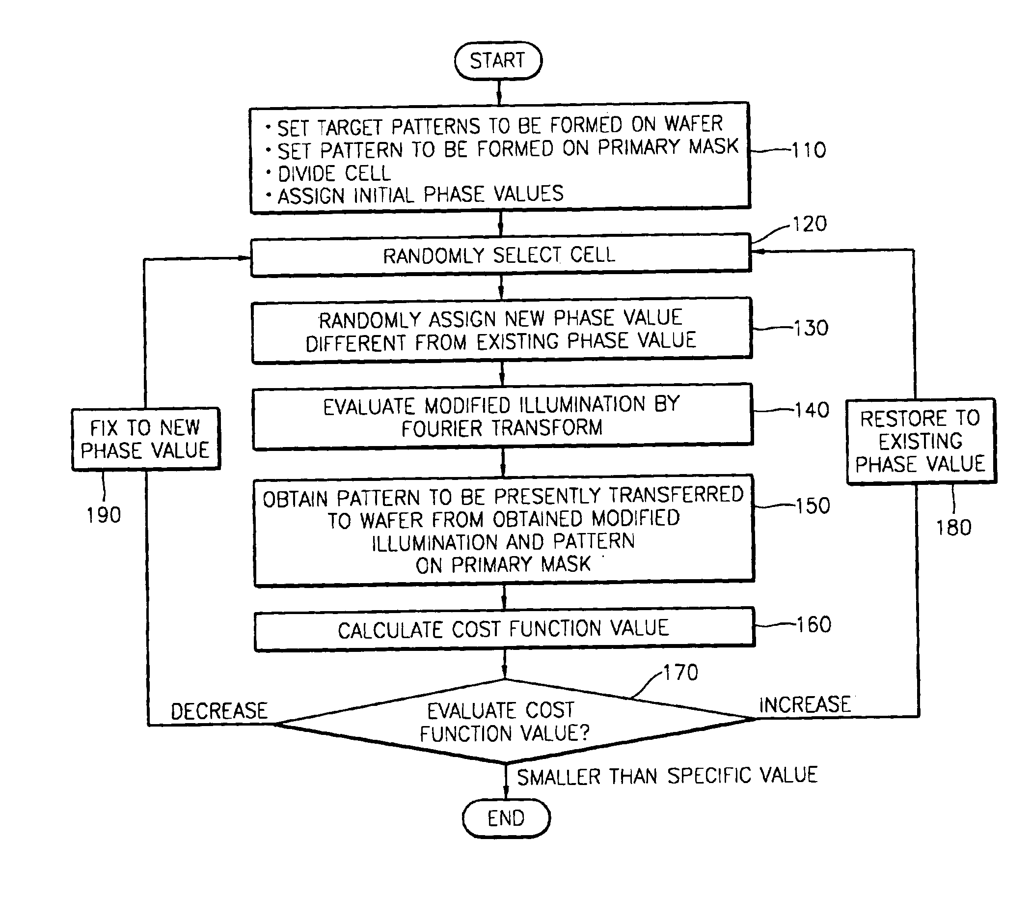
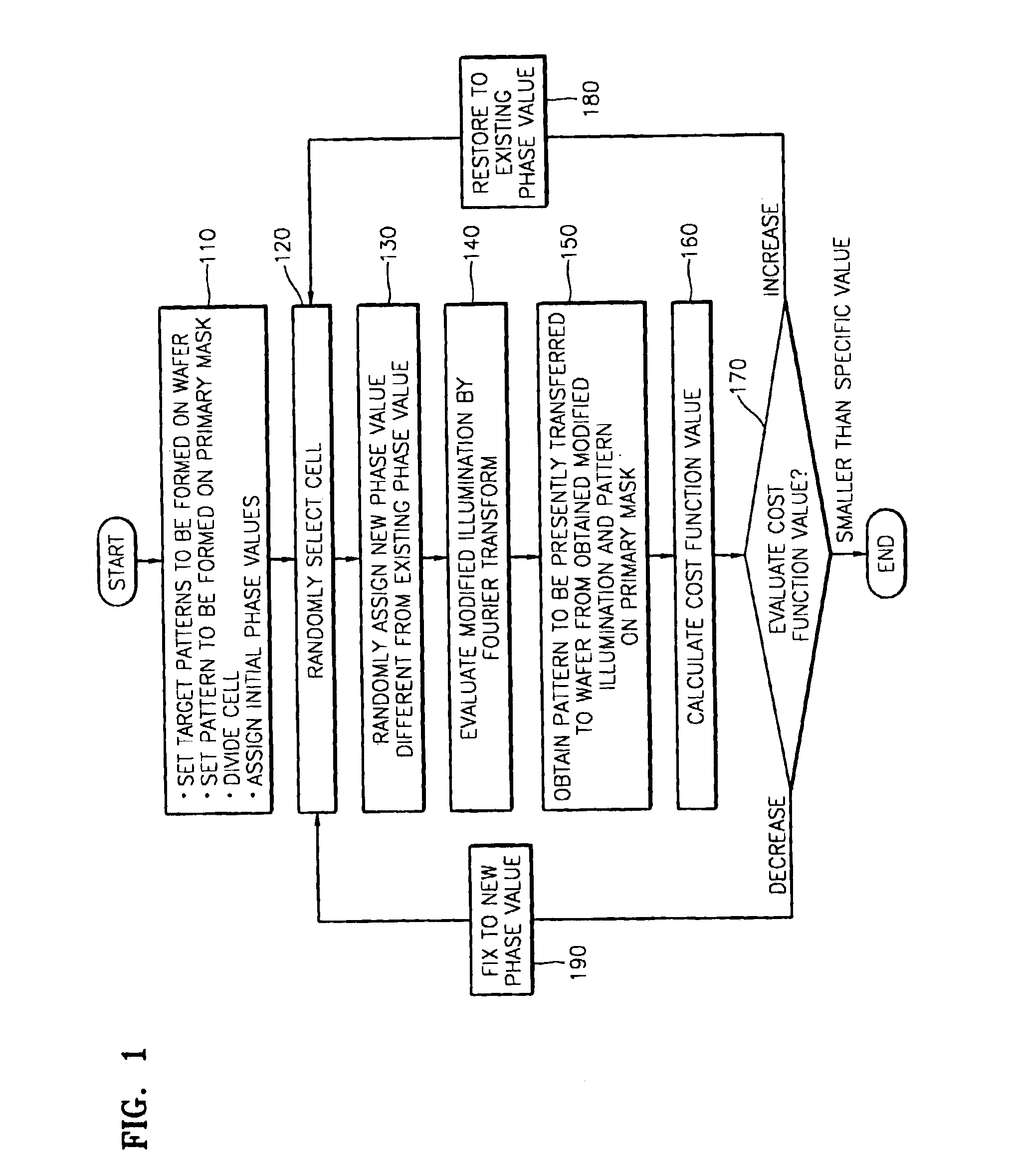
[0032]The present invention provides a method of designing a phase grating pattern for providing an optimum form of modified illumination to a primary mask, i.e., the mask that bears the pattern to be transcribed onto a wafer in a photolithographic process. More specifically, the modified illumination provided by the phase grating pattern causes an image of the mask pattern to be transferred to the wafer in a manner optimal for producing the desired patterns on the wafer. To this end, the phase grating diffracts light from the light source of the exposure apparatus, whereby the characteristics of the light passing therethrough are modified in a way that effects an optimal transfer of the pattern of the primary mask to th...


PUM

PropertyMeasurementUnit
widthaaaaaaaaaa
widthaaaaaaaaaa
depthaaaaaaaaaa

Abstract

A method of designing a phase grating pattern provides a modified form of illumination for a main mask, optimum for producing one or more target patterns on a wafer in a photolithographic process. Once the target pattern(s) to be formed on the wafer are decided, an area to be occupied by at least a portion of the phase grating is divided into a plurality of subcells, initial phase values are assigned to each of the subcells, and one of the subcells is randomly selected and the phase value last assigned thereto is changed, and the process is repeated. The process is in an iteration that changes the arrangement of the phase values assigned to the subcells until they converge on one which will provide the design for a phase grating which will produce a modified form of illumination optimum for use in forming the target pattern(s) on the wafer.

Description

BACKGROUND OF THE INVENTION[0001]1. Field of the Invention[0002]The present invention relates to a photolithographic process used in semiconductor manufacturing. More particularly, the present invention relates to a phase grating pattern used to produce modified illumination in a photo mask system and to a method of manufacturing a photo mask system having the phase grating pattern.[0003]2. Description of the Related Art[0004]A photolithographic process is used extensively to transfer pattern images in the manufacturing of semiconductor devices. However, the resolution of the photolithographic process must be increased to meet the current demand for semiconductor devices having higher and higher integration densities, i.e., to meet the demand for manufacturing semiconductor devices produced under smaller and smaller design rules. The resolution of the photolithographic process may be limited by several factors, such as the wavelength of an exposure light source, the numerical apertu...

Claims


Application Information

Patent Timeline
Patent Type & Authority Patents(United States)
IPC IPC(8): G01F9/00G03B27/42G02B5/18G03F9/00G03F7/20G02B6/124G03F1/00G03F1/08G06F17/50H01L21/027H01L21/02G03F1/68G03F1/76
CPCG03F7/70091G03F7/70433G03F7/7015G03F7/70158G03F7/70125G03F1/144G03F1/50H01L21/027
Inventor KANG, YOUNG-SEOGPARK, JONG-RAK
Owner SAMSUNG ELECTRONICS CO LTD
Why Eureka
Try Eureka