Anti-wrong installation method, product and product design method of spline-connected anti-roll torsion bar

An anti-roll torsion bar and spline connection technology, applied in the direction of the lateral relative movement device between the underframe and the bogie, can solve the problems affecting the service life of the product, the height difference of the connection holes, and affecting the driving safety, etc. Achieve the effect of prolonging service life, long service life and simple processing technology

Active Publication Date: 2019-07-02
ZHUZHOU TIMES NEW MATERIALS TECH
View PDF7 Cites 0 Cited by
  • Summary
  • Abstract
  • Description
  • Claims
  • Application Information

AI Technical Summary

Problems solved by technology

[0005] 1. The torsion bar shaft has an initial stress, which may exceed the strength limit of the product after being superimposed with the fatigue stress during use, causing premature failure of the torsion bar shaft and other anti-roll torsion bar device components, affecting driving safety;
[0006] 2. The torsion bar shaft has an initial stress, which makes it deviate from the initial design purpose of the anti-roll torsion bar device not to provide any additional force or torque for several other movements except roll, and has no effect on the movement of the vehicle in six directions. had an impact
[0009] 1. Engraving marks on tooth tops or tooth grooves will easily lead to stress concentration, which will affect the service life of the product, especially when the spline position is not at the end of the torsion bar shaft
[0010] 2. It cannot be hard-wrong-proof, and workers may misassemble. For example, if the marking on the end face of the torsion bar shaft is not aligned along the axial direction, there will be a height difference between the torsion arm at both ends of the torsion bar shaft and the connecting hole of the connecting rod assembly. value

Method used


Image

  • Anti-wrong installation method, product and product design method of spline-connected anti-roll torsion bar
  • Anti-wrong installation method, product and product design method of spline-connected anti-roll torsion bar
  • Anti-wrong installation method, product and product design method of spline-connected anti-roll torsion bar

Examples


Embodiment Construction

[0045] Attached below Figures 2 to 9 The embodiments of the present invention will be described in detail.

[0046] The anti-wrong installation method of splined anti-roll torsion bar is characterized in that the steps are as follows:

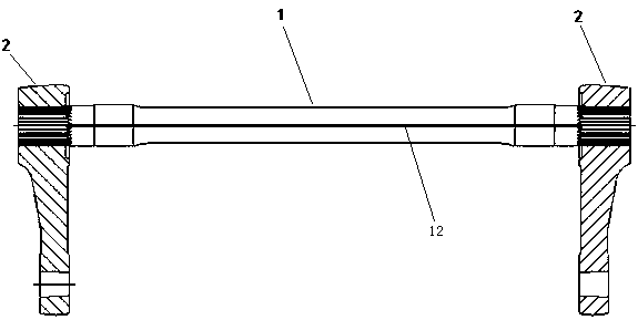
[0047] (1) An external spline 11 is processed at one end of the torsion bar shaft 1, and at least one special spline 11.1 is processed on the external spline 11, and the tooth height of the special spline 11.1 is smaller than that of the ordinary spline;

[0048] (2) Draw the marking line 12 axially on the inner side of the special tooth 11.1, and the marking line 12 extends to the other end of the torsion bar shaft 1;

[0049] (3) Machining an external spline 11 at the other end of the torsion bar shaft 1, and machining a special spline 11.1 axially aligned with the marking line 12 on the external spline 11;

[0050] (4) In the inner wall of the end of the spline connection between the torsion arm 2 and the torsion bar shaft 1, the inner sp...


PUM


Abstract

A mistaken installation preventing method of a spline connected anti-side-rolling torsion bar comprises the following steps that an outer spline is machined at one end of a torsion bar shaft, at least one special key tooth is machined on the outer spline, wherein the tooth height of the special key tooth is smaller than that of a common spline tooth; a marker line is drawn on the inner side of the special key tooth in the axial direction and extends to the other end of the torsion bar shaft; an outer spline is machined at the other end of the torsion bar shaft, a special key tooth axially aligned to the marker line is machined on the outer spline; an inner spline matched with the outer spline is machined in the inner wall of the end, connected with the spline of the torsion bar shaft, of a torsion arm, a special tooth groove matched with the special key tooth is machined on the inner spline, and the tooth groove depth of the special tooth groove is smaller than that of a common inner spline groove; two ends of the torsion bar shaft are sleeved with a torsion arm respectively, and the special tooth groove is matched with the special key tooth, so that the ends, assembled with connecting rod components, of the two torsion arms are aligned in the axial direction. The invention further provides an anti-side-rolling torsion bar and a design method thereof.

Description

technical field [0001] The invention relates to a method for anti-mistake installation of a spline-connected anti-roll torsion bar, which belongs to the field of rail vehicle anti-roll torsion bar assembly. The invention also relates to an anti-roll torsion bar and a design method thereof. Background technique [0002] The vibration of rail vehicles mainly has six degrees of freedom: stretching vibration in the X direction, yaw vibration in the Y direction, ups and downs vibration in the Z direction, nodding vibration around the Y axis, shaking head vibration around the Z axis, and vibration around the X axis. Rolling vibration. The current bogies of rail transit vehicles are all two-stage suspensions, and the anti-roll torsion bar system plays a role in adjusting the roll stiffness of the vehicle and controlling the roll vibration of the vehicle. [0003] The mechanism kinematic diagram of the anti-roll torsion bar system, such as figure 1 As shown, M in the figure is the...

Claims


Application Information

Patent Timeline
Patent Type & Authority Patents(China)
IPC IPC(8): B61F5/24
CPCB61F5/24
Inventor 刘文松罗燕聂清明罗斌杜方孟邹敏佳范湘荣继刚
Owner ZHUZHOU TIMES NEW MATERIALS TECH
Why Eureka
Try Eureka