Supercharge Your Innovation With Domain-Expert AI Agents!

Safety valve and air brake system

A safety valve and valve body technology, which is applied in safety valves, valve devices, balance valves, etc., can solve problems such as difficulty in opening and closing pressure control, leakage of exhaust valves, scratches on grinding surfaces, etc., and achieve improved sealing and braking effects , Facilitate pipeline pressure and improve the effect of sealing performance

Active Publication Date: 2019-11-22
MEISHAN CRRC BRAKE SCI & TECH CO LTD
View PDF5 Cites 0 Cited by
  • Summary
  • Abstract
  • Description
  • Claims
  • Application Information

AI Technical Summary

Problems solved by technology

[0003] The existing safety valve exhaust valve is a sealing belt formed by metal grinding surface. After a certain period of use, scratches will appear on the grinding surface, causing leakage at the exhaust valve. The durability is not high and the maintenance is difficult.
Secondly, the opening and closing pressure of the safety valve are adjusted by the pressure regulating spring on the upper part of the exhaust valve, so it is difficult to control the opening and closing pressure

Method used


Image

  • Safety valve and air brake system
  • Safety valve and air brake system
  • Safety valve and air brake system

Examples


no. 1 example

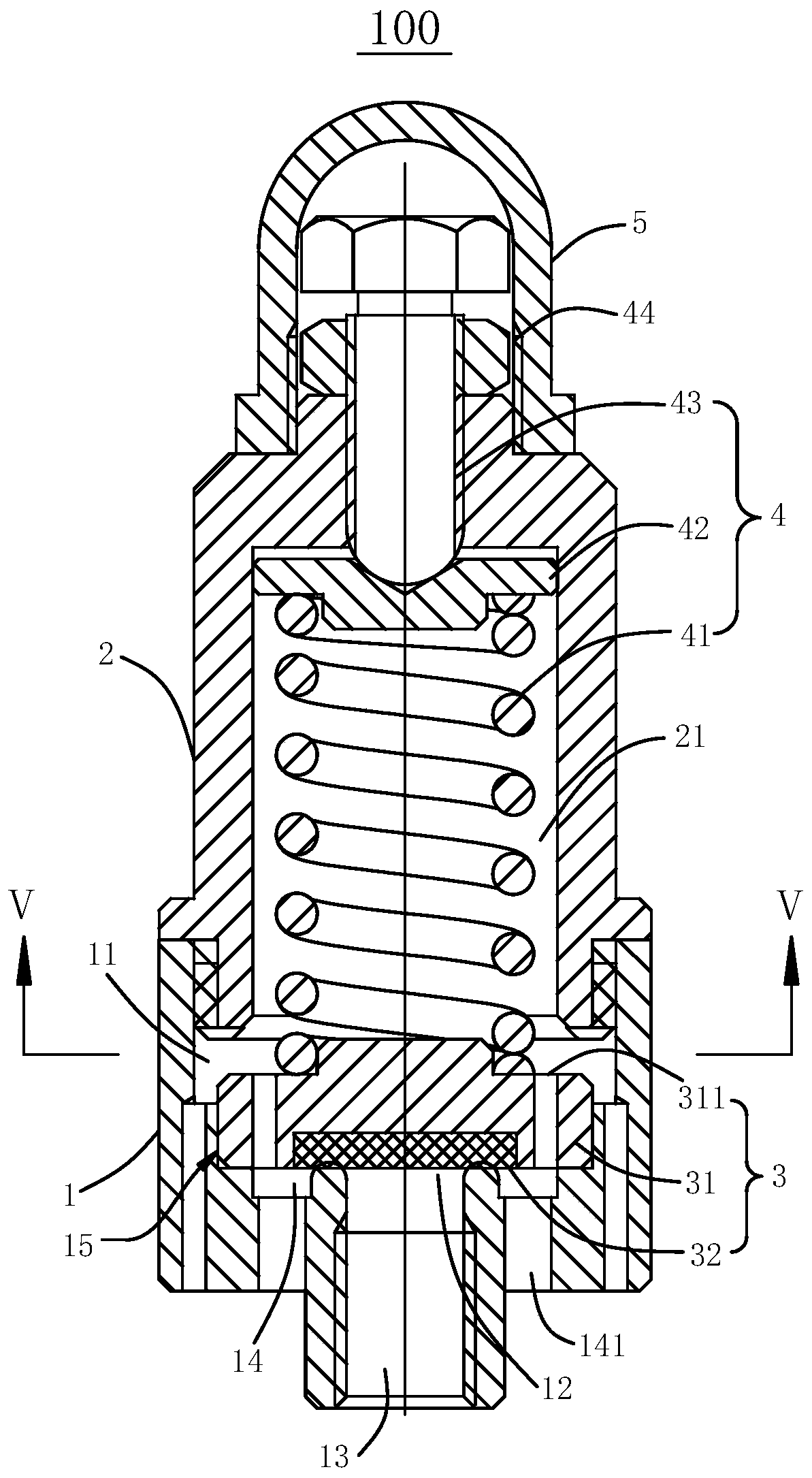
[0033] Please refer to figure 1 , this embodiment provides a safety valve 100 , including a valve body 1 , a spring box 2 , a sandwich valve 3 and a return assembly 4 .

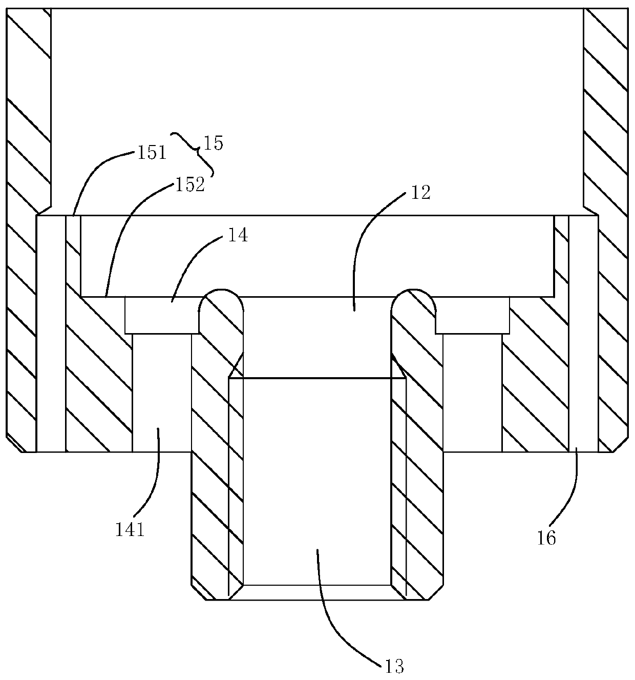
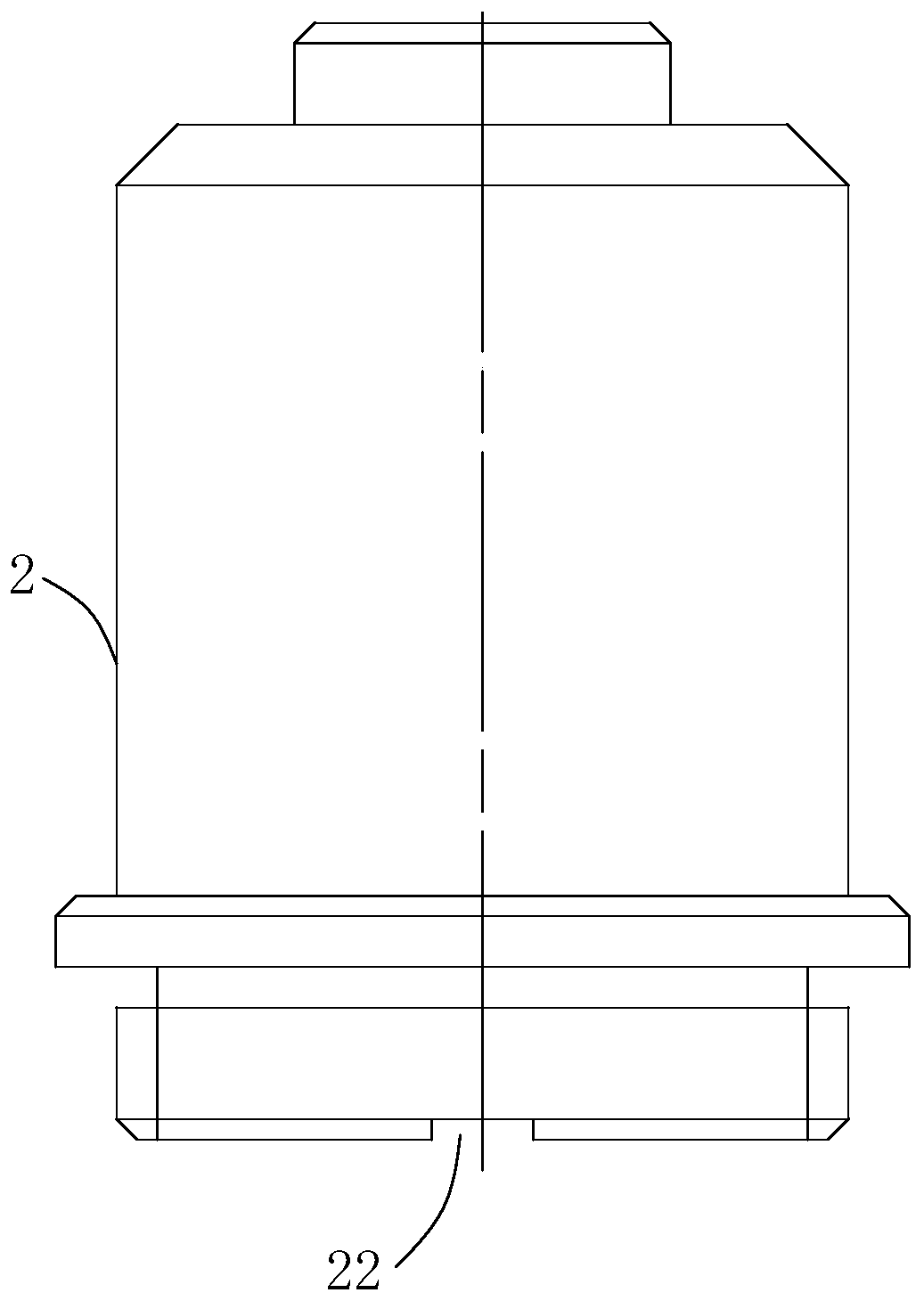
[0034] In this embodiment, the valve body 1 cooperates with the spring box 2 to form an active cavity 11 inside the two, and the valve port 12 communicates with the active cavity 11. The sandwich valve 3 is slidably arranged in the active cavity 11. The sandwich valve 3 includes a valve The core 31 and the rubber gasket 32, the rubber gasket 32 ​​is embedded in the valve core 31, the spring box 2 is provided with an accommodating chamber 21 communicating with the movable chamber 11, the return assembly 4 is slidably arranged in the accommodating chamber 21, and the return assembly The two ends of 4 are respectively connected with the spring box 2 and the valve core 31, and the return component 4 applies the force applied to the valve core 31 to move toward the valve port 12, and is used to drive the rubber ga...

no. 2 example

[0063] This embodiment provides an air braking system, including the safety valve 100 provided in the first embodiment.

[0064] In this embodiment, the air brake system, since the pipeline pressure is provided by compressed air, therefore, the setting of the safety valve 100 can improve the pressure control of the pipeline. The safety valve 100 has a good sealing and braking effect, can effectively protect the pressure of the pipeline, is convenient to adjust the pressure, and improves the control ability.


PUM


Abstract

The invention relates to a safety valve and an air brake system, and belongs to the technical field of air brake equipment. The safety valve comprises a valve body, a spring box, a sandwich valve and a return assembly, wherein the valve body is detachably connected with the spring box; a movable cavity is formed between the valve body and the spring box; a valve opening of the valve body communicates with the movable cavity; the sandwich valve can be arranged in the movable cavity in a sliding mode; the sandwich valve comprises a valve element and a rubber sealing pad; the rubber sealing pad is embedded into the valve element; the spring box comprises an accommodating cavity with an opening in one end; the return assembly can be arranged in the accommodating cavity in the sliding mode; the two ends of the return assembly are separately connected with the valve element and the spring box; and the return assembly is used for driving the valve element to move towards the valve opening, so that the rubber sealing pad abuts against the valve opening to seal the valve opening. The safety valve of the structure improves the sealing property of the valve opening, and opening pressure and closing pressure of the safety valve can be separately regulated for conveniently realizing pressure control on the safety valve. The air brake system applying the safety valve improves the sealing braking effect, so that an operator conveniently controls pipeline pressure.

Description

technical field [0001] The invention relates to the technical field of air brake equipment, in particular to a safety valve and an air brake system. Background technique [0002] With the development of science and technology, the application range of safety valves is becoming wider and wider. The safety valve is used to limit the air pressure, discharge the pressure exceeding the set value to the atmosphere, and reduce the pressure to within the set value range, and the set value can be adjusted. [0003] The exhaust valve of the existing safety valve is a sealing belt formed by the metal grinding surface. After a certain period of use, scratches will appear on the grinding surface, causing leakage at the exhaust valve. The durability is not high and the maintenance is difficult. Secondly, the opening and closing pressure of the safety valve are all adjusted by the pressure regulating spring on the upper part of the exhaust valve, so it is difficult to control the opening ...

Claims


Application Information

Patent Timeline
Patent Type & Authority Patents(China)
IPC IPC(8): F16K17/04F16K17/08
CPCF16K17/048F16K17/08
Inventor 李谋逵全琼张宇朱宇刘毅韦雪丽宁波张靖罗玮杨金龙杜霞安鸿肖维远吕超申燕飞
Owner MEISHAN CRRC BRAKE SCI & TECH CO LTD
Features
  • R&D
  • Intellectual Property
  • Life Sciences
  • Materials
  • Tech Scout
  • Unparalleled Data Quality
  • Higher Quality Content
  • 60% Fewer Hallucinations
Learn More