Method for measuring radar cross section by using extrapolation method

A radar scattering and cross-sectional area technology, applied in the radar field, can solve the problems of lack of RCS measurement system calibration information, large measurement result uncertainty, and small electromagnetic wave reflection, etc., to achieve rich RCS measurement information, comprehensive measurement result information, and small measurement The effect of uncertainty

Active Publication Date: 2017-09-22
NAT INST OF METROLOGY CHINA
View PDF6 Cites 3 Cited by
  • Summary
  • Abstract
  • Description
  • Claims
  • Application Information

AI Technical Summary

Problems solved by technology

The disadvantage of using a sphere to calibrate the RCS measurement system is that since the sphere is a sphere in all viewing directions, there is no change in the 360-degree rotation of the RCS, thus lacking calibration information for the azimuth and elevation angles of the RCS measurement system
In addition, the sphere has little reflection of the received electromagnetic wave, so that the signal-to-noise ratio (SNR) and signal-to-clutter ratio (SCR) of the measurement signal are low, which will cause the measurement sensitivity of the calibrated RCS measurement system to be low, and the measurement results are uncertain big
[0003] If other reflectors with angle RCS information are used to calibrate the RCS measurement system, the RCS value of the reflector must be known first, and the accurate RCS value of complex geometry cannot be obtained at present

Method used


Image

  • Method for measuring radar cross section by using extrapolation method
  • Method for measuring radar cross section by using extrapolation method
  • Method for measuring radar cross section by using extrapolation method

Examples


Embodiment Construction

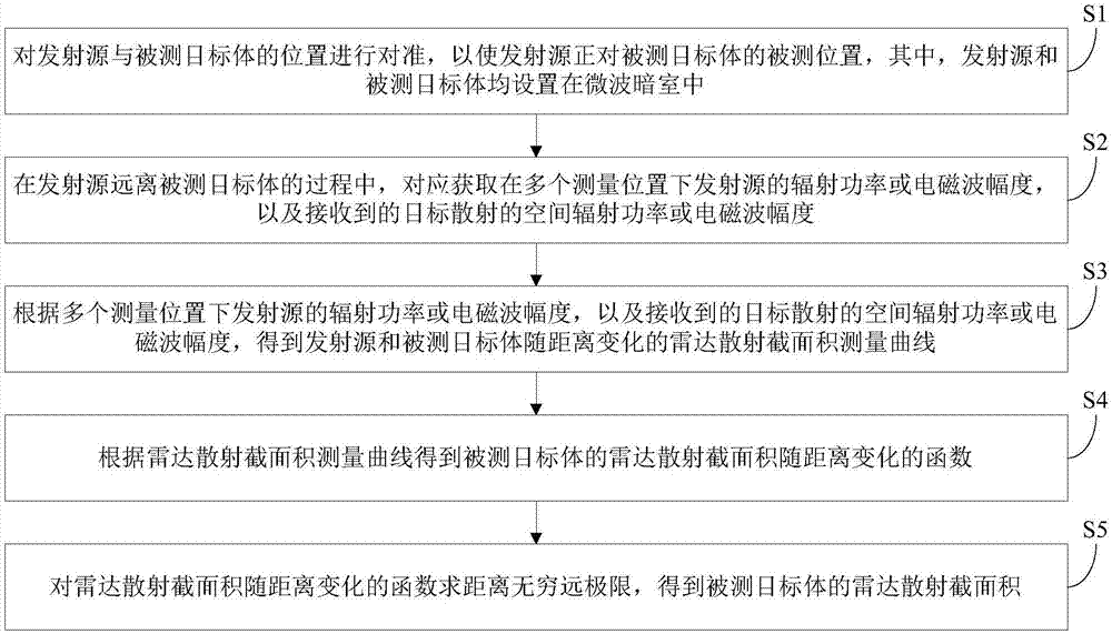
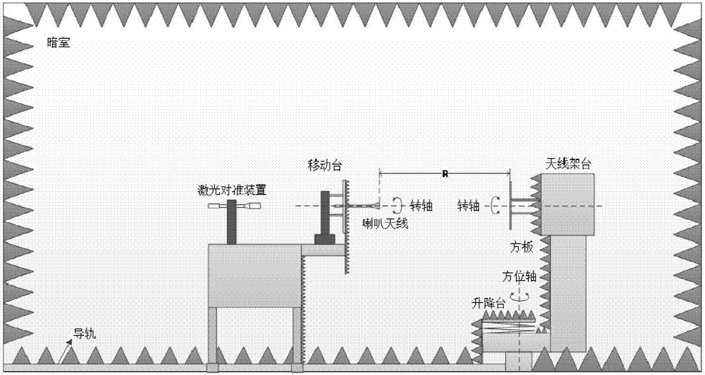
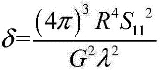
[0019] The embodiments of the present invention are described in detail below. Examples of the embodiments are shown in the accompanying drawings, in which the same or similar reference numerals indicate the same or similar elements or elements with the same or similar functions. The embodiments described below with reference to the drawings are exemplary, and are only used to explain the present invention, but should not be understood as limiting the present invention.

[0020] In the description of the present invention, it should be understood that the terms "center", "longitudinal", "transverse", "upper", "lower", "front", "rear", "left", "right", " The orientation or positional relationship indicated by "vertical", "horizontal", "top", "bottom", "inner", "outer" etc. is based on the orientation or positional relationship shown in the drawings, and is only for the convenience of describing the present invention and The description is simplified, rather than indicating or impl...


PUM


Abstract

The invention discloses a method for measuring a radar cross section by using an extrapolation method. The method includes the following steps that: the position of a transmitting source is aligned with the position of a measured target, so that the transmitting source can be aligned with the measured position of the measured target; in a process in which the transmitting source leaves the measured target, the radiation power or electromagnetic wave amplitudes of the transmitting source under a plurality of measurement positions and received spatial radiation power or electromagnetic wave amplitudes which are scattered by the target are correspondingly obtained; a radar cross section measurement curve which changes with the distance of the transmitting source and measured target is obtained according to the radiation power or electromagnetic wave amplitudes of the transmitting source under the plurality of measurement positions and the received spatial radiation power or electromagnetic wave amplitudes which are scattered by the target; the function of the change of the radar cross section of the measured target with the distance is obtained according to the radar cross section measurement curve; and the distance infinity limit of the function is solved, so that the radar cross section of the measured target can be obtained. The method has the advantages of high measurement accuracy and wide application range.

Description

Technical field [0001] The invention relates to the field of radar technology, in particular to an extrapolation method for measuring radar cross-sectional area. Background technique [0002] The current radar cross-sectional area (RCS) measurement method is to calibrate the entire test system (or "calibration", "calibration") through a sphere, and perform RCS measurements on the sphere and the measured target in the test field. By comparison, the RCS value of the measured target is obtained. The RCS value of the sphere is calculated by theory (metal ball: Pi*r^2, r is the radius of the sphere). The disadvantage of using a sphere to calibrate the RCS measurement system is that because the sphere is a sphere in all observation directions, the RCS does not change when rotating 360 degrees, so there is a lack of calibration information for the azimuth and pitch angles of the RCS measurement system. In addition, the sphere has little reflection on the received electromagnetic waves,...

Claims


Application Information

Patent Timeline
Patent Type & Authority Applications(China)
IPC IPC(8): G01S7/40
CPCG01S7/4004
Inventor 崔孝海袁文泽李勇魏广宇高小珣
Owner NAT INST OF METROLOGY CHINA
Why Eureka
Try Eureka