Hydraulic linkage counter-blow hammer

A hydraulic linkage and counter-hammer technology, which is applied in the field of casting stamping, can solve the problems of low energy profit margin, jamming, and large structural size, and achieve the effects of high efficiency, effective stroke, and high accuracy

Inactive Publication Date: 2017-09-26
陈加奎
View PDF5 Cites 0 Cited by
  • Summary
  • Abstract
  • Description
  • Claims
  • Application Information

AI Technical Summary

Problems solved by technology

[0002] The traditional hammer power uses compressed air or steam. Due to the large compressed air or steam transmission pipeline, there is a large amount of leakage, and the energy profit margin is very low. At the same time, a large amount of waste gas or waste water is discharged during the working process, which pollutes the environment; in addition The traditional linkage of the upper and lower hammer heads of the counter hammer uses a steel belt or a wire rope to achieve linkage. This structural equipment has a large structural size and a short service life of the steel belt or wire rope. Once the steel belt or wire rope breaks, safety accidents will occur. When in use, the service life of the hammer head is short and cannot meet the requirements of use; at the same time, the general counter hammer does not have a stroke alarm device, which often causes the situation of being stuck due to excessive expansion and contraction after long-term use; and now Some hammers are completed in the form of manual control, which greatly increases the cost of investment and wastes human resources

Method used


Image

  • Hydraulic linkage counter-blow hammer

Examples


Embodiment Construction

[0013] Below in conjunction with accompanying drawing and embodiment the present invention is described in further detail:

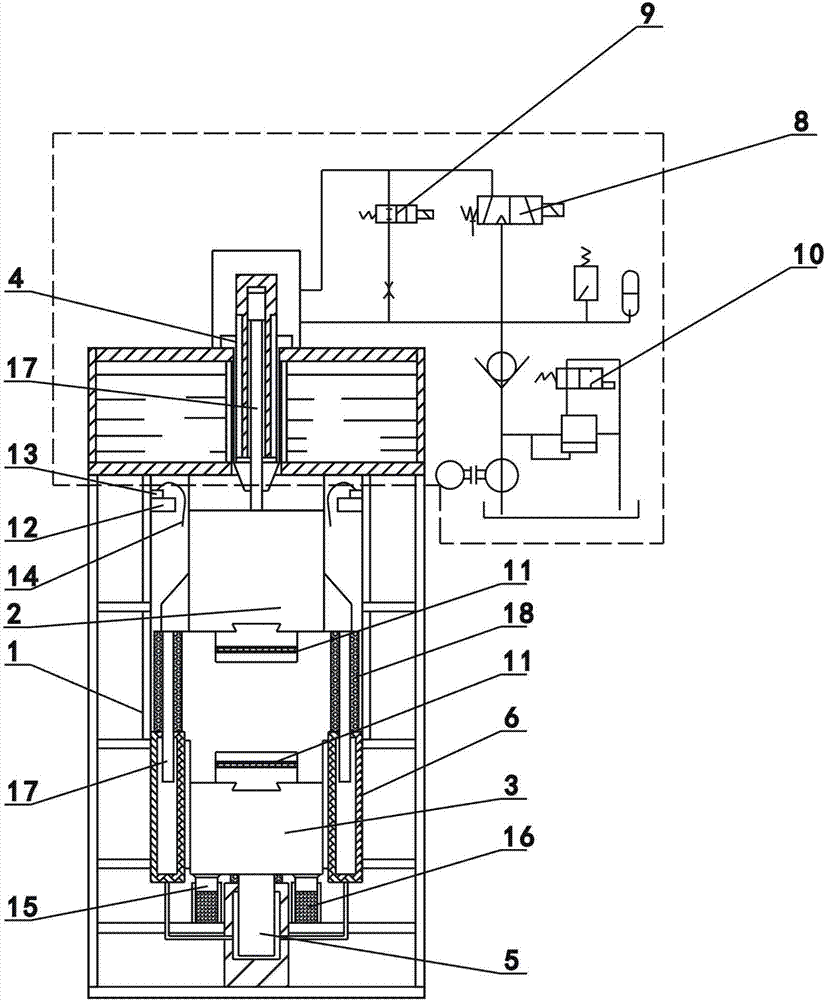
[0014] As an embodiment of the hydraulic linkage counter hammer of the present invention, such as figure 1 As shown, it includes a frame body 1, an upper hammer head 2, a lower hammer head 3, an upper hydraulic linkage cylinder 4, a lower hydraulic linkage cylinder 5, a middle hydraulic linkage cylinder 6 and an electromagnetic control system 7. The upper hammer head 2 and the lower hammer The head 3 is arranged inside the frame body 1 and moves up and down along the frame body 1. The upper hammer head 2 is provided with the upper hydraulic linkage oil cylinder 4, and the upper hydraulic linkage oil cylinder 4 drives the upper hammer head 2. The hammer head 2 moves up and down, the lower part of the lower hammer head 3 is provided with the lower hydraulic linkage oil cylinder 5, and the lower hydraulic linkage oil cylinder 5 drives the lower hammer head ...


PUM


Abstract

The invention relates to the technical field of casting stamping, in particular to a hydraulic linkage counter hammer. The hydraulic linkage counter hammer includes a frame body, an upper hammer head, a lower hammer head, an upper hydraulic linkage cylinder, a lower hydraulic linkage cylinder, a middle hydraulic linkage cylinder and an electromagnetic control system. linkage oil cylinder, the upper hydraulic linkage oil cylinder drives the upper hammer head to move up and down, the lower part of the lower hammer head is provided with the lower hydraulic linkage oil cylinder, and the lower hydraulic linkage oil cylinder drives the lower hammer head to move up and down, so The middle hydraulic linkage oil cylinder is arranged between the upper hammer head and the lower hammer head, and the electromagnetic control system includes a first electromagnetic valve, a second electromagnetic valve and a third electromagnetic valve, and the first electromagnetic valve is connected with the upper hammer head. The hydraulic linkage oil cylinder is electrically connected, the second electromagnetic valve is electrically connected to the lower hydraulic linkage oil cylinder, and the third electromagnetic valve is electrically connected to the middle hydraulic linkage oil cylinder.

Description

technical field [0001] The invention relates to the technical field of casting stamping, in particular to a hydraulic linkage counter hammer. Background technique [0002] The traditional hammer power uses compressed air or steam. Due to the large compressed air or steam transmission pipeline, there is a large amount of leakage, and the energy profit margin is very low. At the same time, a large amount of waste gas or waste water is discharged during the working process, which pollutes the environment; in addition The traditional linkage of the upper and lower hammer heads of the counter hammer uses a steel belt or a wire rope to achieve linkage. This structural equipment has a large structural size and a short service life of the steel belt or wire rope. Once the steel belt or wire rope breaks, safety accidents will occur. When in use, the service life of the hammer head is short and cannot meet the requirements of use; at the same time, the general counter hammer does not ...

Claims


Application Information

Patent Timeline
Patent Type & Authority Applications(China)
IPC IPC(8): B21J7/28B21J7/46
CPCB21J7/28B21J7/46
Inventor 陈加奎
Owner 陈加奎
Why Eureka
Try Eureka