AI technical title is built by Patsnap AI team. It summarizes the technical point description of the patent document.
A multi-legged robot and connecting rod technology, applied in the field of robotics, can solve problems such as restricting the movement space of the feet, achieve good dynamic response ability, increase transmission distance, and reduce weight
Inactive Publication Date: 2019-04-23
SHANGHAI UNIV
View PDF6 Cites 2 Cited by
Summary
Abstract
Description
Claims
Application Information
AI Technical Summary
This helps you quickly interpret patents by identifying the three key elements:
Problems solved by technology
Method used
Benefits of technology
Problems solved by technology
This structure has good rigidity and bearing capacity, but it needs to have more than two linear drive units, and the transmission distance of the connecting rod restricts the movement space of the foot end
Method used
Image
Click on the blue label to locate the original text in one second.
Reading with bidirectional positioning of images and text.
Examples
Embodiment 1
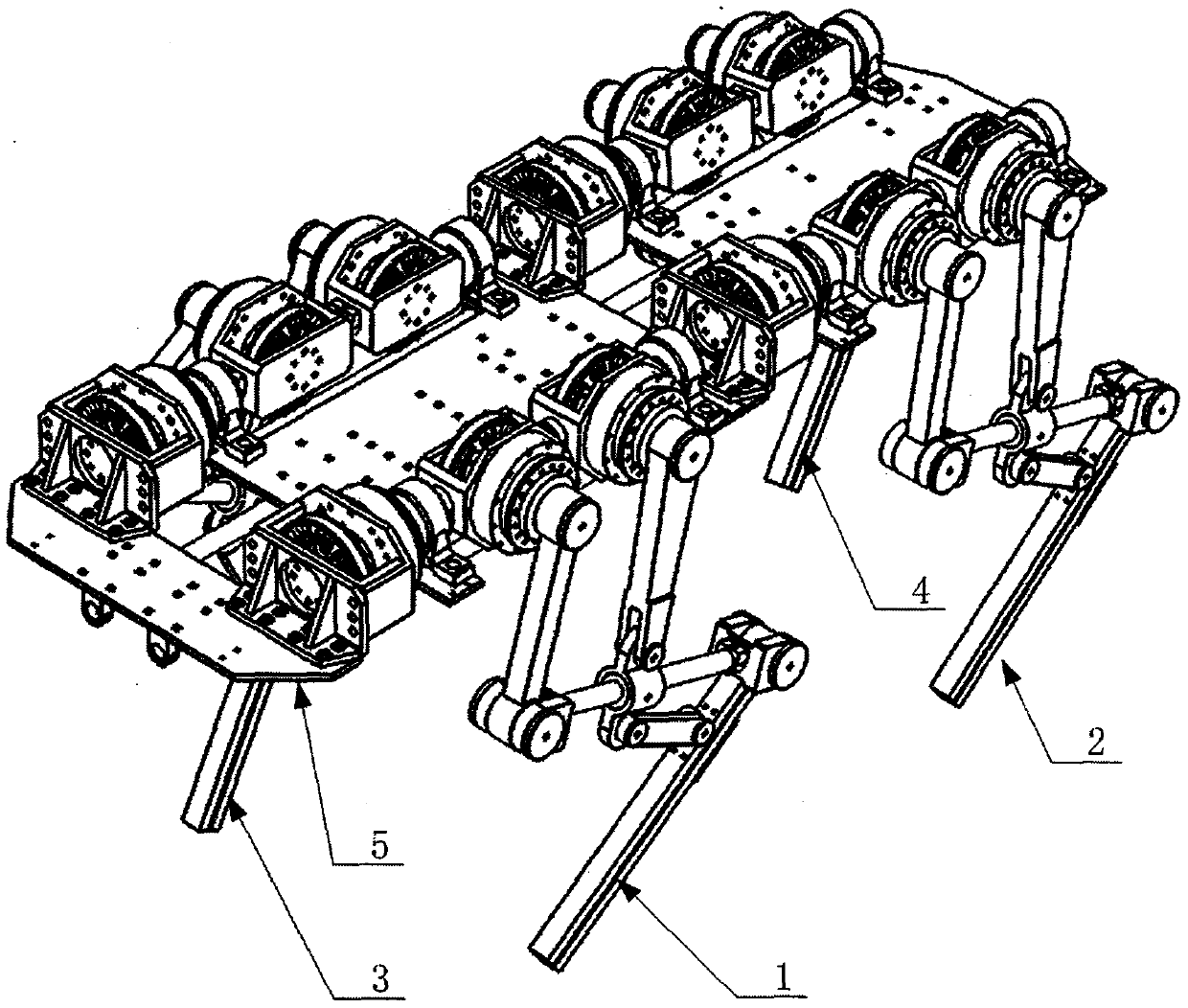
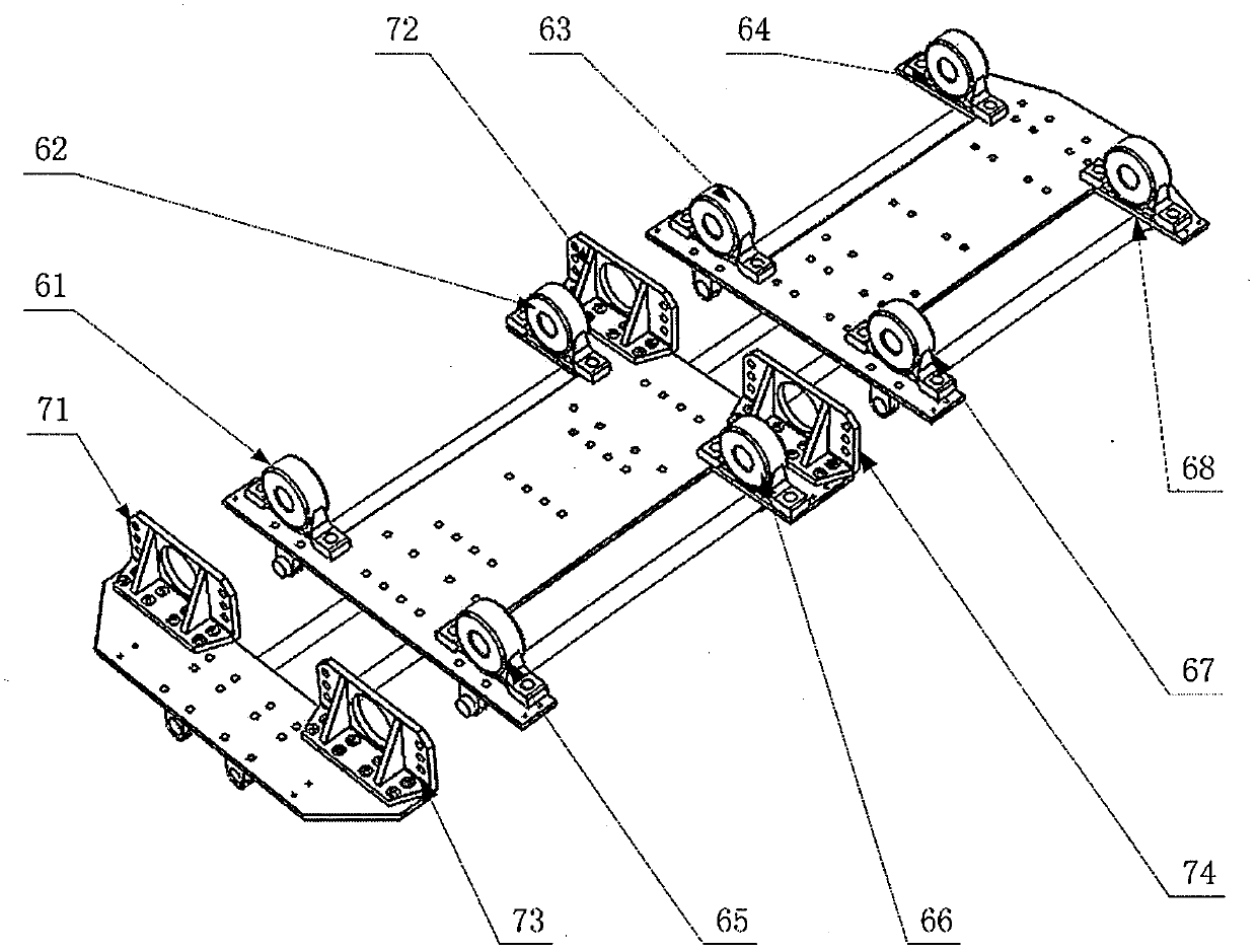
[0026] Such as figure 1 , figure 2 As shown, the robot includes a left front foot unit 1, a left rear foot unit 2, a right front foot unit 3, a right rear foot unit 4, and a frame unit 5, wherein the frame unit 5 includes a front base plate 513, a middle base plate 512, a rear base plate 511, the first connecting rod 521, the second connecting rod 522, the third connecting rod 523, the fourth connecting rod 524, the fifth connecting rod 525, the sixth connecting rod 526, the first connecting member 5301, the second connecting member 5302, The third connecting piece 5303, the fourth connecting piece 5304, the fifth connecting piece 5305, the sixth connecting piece 5306, the seventh connecting piece 5307, the eighth connecting piece 5308, the ninth connecting piece 5309, the tenth connecting piece 5310, the tenth connecting piece The first connecting piece 5311, the twelfth connecting piece 5312, the thirteenth connecting piece 5313, the fourteenth connecting piece 5314, the f...
Embodiment 2
[0039] Such as Figure 8 As shown in the figure a in the middle, just loosen the limit screw of the bearing end cover, the connecting rod of the thigh joint and the connecting rod of the lower leg joint are separated from the output shaft of the reducer in the driving structure of the thigh joint and the output shaft of the reducer in the driving structure of the lower leg joint respectively , can realize the rapid separation of the driving structure and the transmission structure in the right forefoot unit.
[0040] Such as Figure 8 As shown in figure b in the middle, the transmission structure of the right forefoot unit 3 is turned over along the horizontal plane during assembly, so that the deformation from the elbow joint to the knee joint can be realized.
[0041] Such as Figure 8 As shown in figure c in the middle, connect the connecting rod of the thigh joint and the connecting rod of the lower leg to the output shaft of the reducer in the driving structure of the t...
PUM
Abstract
The invention discloses a link-type multi-leg robot which, based on bionic features of quadruped mammals, comprises four sets of foot modules and three-segment frame modules distributed symmetrically on two sides of a frame. The link-type multi-leg robot is characterized in that each foot unit employs a multi-link mechanism having a prismatic pair, and a hip joint, a thigh joint and a knee joint in each foot unit are driven in a transmission manner where an alternating-current permanent magnet synchronous motor and a harmonic reducer are connected; the modular foot design concept may allow foots and the frame to be quickly detached and attached to arrive at different configurations, and accordingly one robot may come with multiple models. The multi-link scaling foot structure used herein allows ratios of force and movement of thigh joints and shank joints to be amplified, and the requirement on motor output torque is lowered. The leg link structure has both high rigidity and bearing capacity. The legs can tolerate driving errors, the rigidity and stability of the whole structure are improved, and the robot is imparted better ability to adapt to complex terrains.
Description
technical field [0001] The invention belongs to the technical field of robots, and in particular relates to a link type multi-legged robot. Background technique [0002] Due to their unique body structure, multi-legged mammals have high dynamics, high stability, and high adaptability for locomotion. The multi-legged robot with bionic features developed by referring to bionics can not only realize dynamic walking, but also move at high speed. Traditional mobile robots such as existing wheeled and tracked robots need to keep in contact with the ground when moving, but footed robots can use isolated ground support instead of continuous support, and select the optimal support point in complex terrain to achieve Greater mobility and adaptability. If the auxiliary execution tool is combined with the motion platform composed of multi-legged robots, it can replace humans to complete tasks in dangerous environments, so it has broad application prospects. [0003] At present, the l...
Claims
Application Information
Patent Timeline
Application Date:The date an application was filed.
Publication Date:The date a patent or application was officially published.
First Publication Date:The earliest publication date of a patent with the same application number.
Issue Date:Publication date of the patent grant document.
PCT Entry Date:The Entry date of PCT National Phase.
Estimated Expiry Date:The statutory expiry date of a patent right according to the Patent Law, and it is the longest term of protection that the patent right can achieve without the termination of the patent right due to other reasons(Term extension factor has been taken into account ).
Invalid Date:Actual expiry date is based on effective date or publication date of legal transaction data of invalid patent.

