Shaft coupling used between motor rotating shaft and spline connecting shaft

A technology of motor rotating shaft and connecting shaft, applied in rigid shaft couplings, couplings, electric components, etc., can solve the problems of easy sliding, small contact area, few fixed points, etc., to save production costs, expand The effect of versatility and large contact area

Inactive Publication Date: 2017-09-26
HUBEI WEINENGDA TRANSMISSION CO LTD
View PDF0 Cites 5 Cited by
  • Summary
  • Abstract
  • Description
  • Claims
  • Application Information

AI Technical Summary

Problems solved by technology

[0003] Most of the current methods are to fix the shaft coupling on the connecting shaft of the spline to be processed with bolts, which has the following disadvantages: 1. Using the method of bolt fixing, the connecting shaft is partially stressed, the contact area is small, and the splined connecting shaft is easily damaged. When milling splines, spray water on the splines to cool down, and the local contact surface between the bolts of the coupling and the spline connection shaft is easily corroded, which affects the service life of the spline connection shaft; 2. Bolts are used to fix the spline connection shaft It is easy to deviate from the rotation center. When the motor drives the spline connection shaft to rotate, it is easy to cause the spline to vibrate, which is not conducive to the fine processing of complex splines and reduces the precision of spline processing; 3. It is fixed by bolts, with few fixed points and small friction. When rotating, especially when rotating at high speed, it is easy to slip or even slip, which will affect the processing and production

Method used


Image

  • Shaft coupling used between motor rotating shaft and spline connecting shaft
  • Shaft coupling used between motor rotating shaft and spline connecting shaft

Examples


Embodiment Construction

[0018] The present invention is further described below in conjunction with specific embodiment:

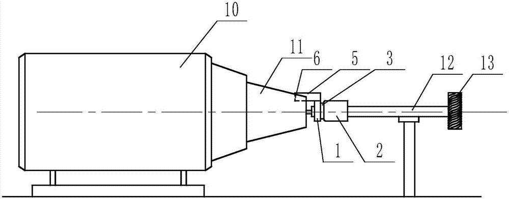
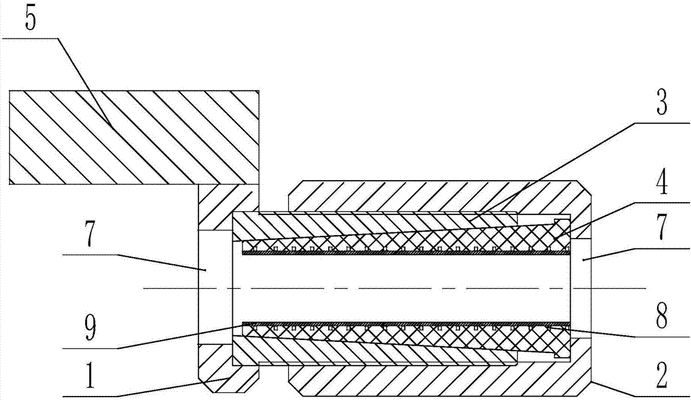
[0019] see figure 1 and figure 2 , a coupling used between the motor rotating shaft and the spline connection shaft, including a left sleeve 1, a right sleeve 2, a shaft sleeve 3 and a tapered sleeve 4, and the outer surface of the left sleeve 1 is welded with The positioning key 4 fixed along the axial direction, the positioning key 4 is clamped in the positioning groove 5 on the motor rotating shaft 11, the shaft sleeve 3 is connected with the left sleeve 1, and the inner side of the right sleeve 2 is provided with an internal thread, which is connected with the shaft sleeve 3 The external threads on the sleeve 3 are matched, the two ends of the shaft sleeve 3 are open, and the inner diameter of the opening at one end of the shaft sleeve 3 in contact with the left sleeve 1 is smaller than the inner diameter of the opening at the other end, forming a conical through hole. The ...


PUM


Abstract

The invention provides a coupling used between the rotating shaft of a motor and a spline connection shaft, which includes a left sleeve, a right sleeve, a shaft sleeve and a tapered sleeve. The outer surface of the left sleeve is welded with a The positioning key, the positioning key is clamped in the positioning groove on the motor rotating shaft, the shaft sleeve is connected with the left sleeve, and the inner side of the right sleeve is provided with an internal thread, which matches the external thread on the shaft sleeve, and the two ends of the sleeve are open , the inner diameter of the opening of one end of the shaft sleeve in contact with the left sleeve is smaller than the inner diameter of the opening of the other end, forming a conical through hole, and a tapered sleeve matching the conical through hole of the shaft sleeve is arranged inside the shaft sleeve. There is a shaft hole, and the end faces of the left sleeve and the right sleeve are provided with a tightening port. The inner diameter of the tightening port is larger than the inner diameter of the shaft hole and smaller than the maximum diameter of the tapered sleeve. Rotate the right sleeve to tighten the tapered sleeve through the tightening port. Squeeze into the bushing. The shaft coupling of the invention has a simple structure, applies force evenly to the spline connection shaft, and has good fixing effect.

Description

technical field [0001] The invention relates to a shaft coupling, in particular to a shaft coupling used between a motor rotating shaft and a spline connection shaft. Background technique [0002] Couplings are used to connect two shafts (drive shaft and driven shaft) in different mechanisms to make them rotate together to transmit torque mechanical parts. In the milling lathe, on the one hand, the specification of the rotating shaft of the motor is fixed, which is different from the specification of the connecting shaft of the spline to be processed, and for different splines, the length of the spline connecting shaft is different; on the other hand, the rotation of the motor The size of the shaft should not be too long. Therefore, a coupling is needed to connect the rotating shaft of the motor with the connecting shaft of the spline to be processed to effectively transmit the rotational motion performance. [0003] Most of the current methods are to fix the shaft coupling...

Claims


Application Information

Patent Timeline
Patent Type & Authority Applications(China)
IPC IPC(8): F16D1/05H02K7/00
CPCF16D1/05H02K7/003
Inventor 王平丁然魏从亮
Owner HUBEI WEINENGDA TRANSMISSION CO LTD
Why Eureka
Try Eureka