
Synchronous belt anti-vibration tensioning device

A technology of tensioning device and synchronous belt, which is applied in the direction of transmission, belt/chain/gear, mechanical equipment, etc., can solve the problems of increased synchronous belt wear, tooth skipping, vibration, etc., to reduce development costs, avoid mechanical interference, The effect of ensuring stability

Pending Publication Date: 2017-09-26
王萌
View PDF9 Cites 12 Cited by
  • Summary
  • Abstract
  • Description
  • Claims
  • Application Information

AI Technical Summary

Problems solved by technology

[0002] The characteristics of synchronous belt transmission: stable transmission, low noise, buffer and shock absorption, can allow large center distance transmission, and can slip to protect mechanical parts when overloaded. In the application of synchronous belt transmission, there is a large center distance. Tensioning, the current synchronous belt tensioning is achieved through the tensioning wheel, although it can play a role in tensioning, but the entire transmission device takes up a lot of space, in addition, the tensioning wheel is added to make the synchronous belt contact with the tensioning wheel, increasing the The wear of the synchronous belt is reduced, and its service life is reduced. The transmission is the same, and one side is tensioned. Once the tension is not in place, there will be tooth skipping, which will cause mechanical vibration, especially the impact of skipping teeth on the bearing.

Method used


Image

  • Synchronous belt anti-vibration tensioning device
  • Synchronous belt anti-vibration tensioning device
  • Synchronous belt anti-vibration tensioning device

Examples


Embodiment Construction

[0016] The specific embodiment of the present invention will be described in further detail by describing the embodiments below with reference to the accompanying drawings, the purpose is to help those skilled in the art to have a more complete, accurate and in-depth understanding of the concept and technical solutions of the present invention, and contribute to its implementation.

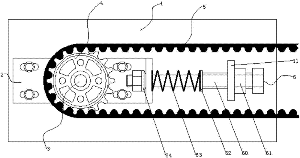
[0017] Such as Figure 1 to Figure 3 It is shown that the present invention is an anti-vibration tensioning device for a synchronous belt, which reduces the wear of the synchronous belt, ensures the reliability of the tension and the performance of anti-mechanical vibration, and avoids the occurrence of tooth skipping of the synchronous belt.

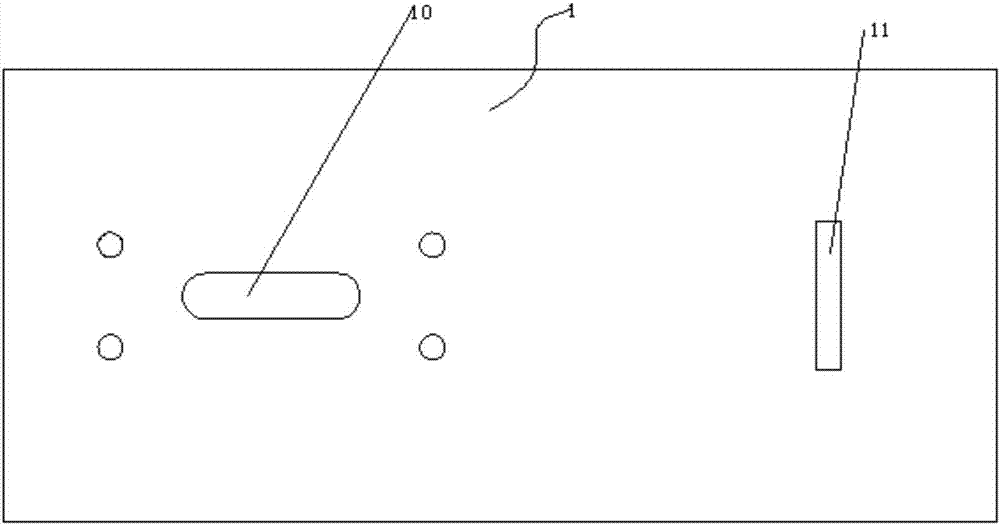
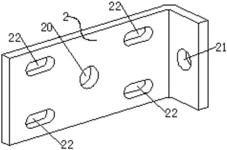
[0018] Specifically, if Figure 1 to Figure 3 shown, including base plate 1, adjusting plate 2, driving shaft 3, synchronous pulley 4, synchronous belt 5 and adjusting structure 6, such as figure 2 As shown, the base plate 1 is provided with a long slott...


PUM


Abstract

The invention discloses a synchronous belt anti-vibration tensioning device. The synchronous belt anti-vibration tensioning device comprises a machine base plate, an adjusting plate, a drive rotating shaft, a synchronous belt wheel, a synchronous belt and an adjusting structure; a first long groove hole and an adjusting fixing plate are arranged on the machine base plate, a shaft hole is formed in the middle of the adjusting plate, an adjusting hole is formed in the adjusting plate, four second long groove holes are formed in the adjusting plate, the adjusting plate and the machine base plate are connected in a manner that bolts penetrate the second long groove holes, the position of the shaft hole corresponds to the position of the first long groove hole in the machine base plate, the drive rotating shaft penetrates the first long groove hole and the shaft hole to be connected with the synchronous belt wheel, the synchronous belt is connected with the synchronous belt wheel, and the adjusting structure is composed of a bolt part, a first tightening nut, a blocking piece, a spring, a membrane spring and a second tightening nut. According to the technical scheme, wear of the synchronous belt is reduced, tensioning reliability and mechanical vibration resistance performance are ensured, and the phenomenon that tooth jumping appears in the synchronous belt is avoided.

Description

technical field [0001] The invention belongs to the technical field of synchronous belt transmission, in particular, the invention relates to an anti-vibration tensioning device for a synchronous belt. Background technique [0002] The characteristics of synchronous belt transmission: stable transmission, low noise, buffer and vibration absorption, can allow large center distance transmission, and can slip to protect mechanical parts when overloaded. In the application of synchronous belt transmission, there is a large center distance. Tensioning, the current synchronous belt tensioning is achieved through the tensioning wheel, although it can play a role in tensioning, but the entire transmission device takes up a lot of space, in addition, the tensioning wheel is added to make the synchronous belt contact with the tensioning wheel, increasing the In order to reduce the wear of the synchronous belt and reduce its service life, the transmission is the same as the one-sided t...

Claims


Application Information

Patent Timeline
IPC IPC(8): F16H7/14
CPCF16H7/0829F16H7/14F16H2007/0865F16H2007/0876F16H2007/0842
Inventor 王萌
Owner 王萌
Learn More