multifunctional test rod

A test rod, multi-functional technology, applied in the direction of TV, closed-circuit television system, electrical components, etc., can solve the problems of difficult test wiring, location in corners, time-consuming and labor-intensive, etc., to achieve convenient image acquisition, convenient wiring operations, and simple structure. Effect

Active Publication Date: 2019-10-29
STATE GRID SHANDONG ELECTRIC POWER COMPANY WEIFANG POWER SUPPLY +1
View PDF7 Cites 0 Cited by
  • Summary
  • Abstract
  • Description
  • Claims
  • Application Information

AI Technical Summary

Problems solved by technology

[0002] Electrical equipment needs to be routinely tested on a regular basis. The main problems in the actual test are as follows: 1) Before the routine test of the equipment, it is necessary to check whether the nameplate information is correct. In the field test, the electrical equipment is often installed in the cabinet or at a high place. Difficult access, such as the transformer cabinet, after the transformer is installed, its nameplate is generally located in the corner, and personnel cannot enter the transformer cabinet to directly view it, resulting in the inability to check the equipment information; 2) Wiring is required during the test, and the current needs to be connected to the terminal of the equipment. There are two wires, the detection line and the voltage detection line. Some equipment in the cabinet or at a slightly higher place outdoors cannot be touched by the staff directly. In some environments, it is difficult and time-consuming to erect ladders. It is relatively high, and the staff cannot reach the clamping part with their hands, and they need to step on a stool to get there. It is very time-consuming and laborious to set up a ladder

Method used


Image

  • multifunctional test rod
  • multifunctional test rod
  • multifunctional test rod

Examples


Embodiment Construction

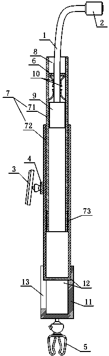
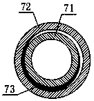
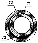
[0033] With reference to the drawings, the multifunctional test rod of the present invention includes a hollow and adjustable length rod body 7, a universal positioning hose 1 is connected to the top of the rod body 7, and the universal positioning hose 1 is slidably installed in the top cavity of the rod body 7. , The inner cavity of the top end of the rod body 7 is equipped with a hose clamping positioning mechanism, the extension end of the universal positioning hose 1 is equipped with a camera box 2, and the camera box 2 is equipped with a camera. The test rod also includes a wireless connection with the camera. The display device 3 that is connected in communication is a handheld device or is detachably clamped on the rod body 7 through a clamp 4. A spring wire clamp 5 is installed at the bottom end of the rod body 7, and a current detection wire and a voltage detection wire are led out from the spring wire clip 5. Among them, in order to illuminate and supplement the ligh...


PUM


Abstract

The invention relates to a multifunctional test bar. The multifunctional test bar comprises a hollow length adjustable bar body, a universal locating flexible tube is connected to the top end of the bar body and is installed in an inner cavity in the top part of the bar body in a sliding manner, a flexible tube clamping and locating mechanism is arranged in the inner cavity in the top end part of the bar body, a camera box is installed at the outer extending end of the universal locating flexible tube, a camera is installed on the camera box, the test bar further comprises display screen equipment in wireless communication connection with the camera, the display screen equipment is handheld or is detachably clamped on the bar body through a clamping seat, a spring cable clamp is installed at the bottom end of the bar body, and a current detection wire and a voltage detection wire are led out from the spring cable clamp. The multifunctional test bar helps to read a name plate rapidly, assists in wiring, is simple in structure, is flexible to operate, and is quite convenient to carry and use.

Description

Technical field [0001] The invention relates to the field of electrical equipment maintenance tools, in particular to a multifunctional test rod. Background technique [0002] Electrical equipment needs to be routinely tested on a regular basis. The main problems in the actual test are as follows: 1) Before the routine test of the equipment, first check whether the nameplate information is correct. In the field test, the electrical equipment is often installed in a cabinet or high place, and the nameplate reads. Difficulties, such as transformer cabinets. After the transformer is installed, the nameplate is usually located in the corner. People cannot enter the transformer cabinet to check directly, resulting in the inability to check the equipment information; 2) Wiring is required in the test and testing, and current needs to be drawn from the equipment terminals. The detection line and the voltage detection line are two lines. Some equipment in the cabinet or at a higher place...

Claims


Application Information

Patent Timeline
Patent Type & Authority Patents(China)
IPC IPC(8): G01R1/04H04N7/18
CPCG01R1/04H04N7/183
Inventor 刘增文刘发成王璟黄学增田野于凯王同泉王琳房林杰寇希尧吴凤鸣王志明王刚高锐丁方殷国亮金鑫王海君高彬岳瑞荣
Owner STATE GRID SHANDONG ELECTRIC POWER COMPANY WEIFANG POWER SUPPLY
Why Eureka
Try Eureka