High-efficiency thyristor valve assembly testing system and testing method
A technology for thyristor converter valve and component testing, which is applied in the direction of single semiconductor device testing, measuring electricity, measuring devices, etc., can solve the problems of cumbersome operation and low efficiency, and achieves reduction of work repetition rate, improvement of test efficiency, and comprehensive electrical performance. The effect of the test
- Summary
- Abstract
- Description
- Claims
- Application Information
AI Technical Summary
Problems solved by technology
Method used
Image

Examples
Embodiment 1
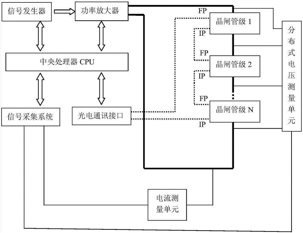
[0036] Such as figure 1 As shown, a high-efficiency thyristor converter valve component testing system includes a signal generation module, a signal acquisition module, a signal processing module, an optical communication control module and a thyristor converter valve component;
[0037] The signal generating module is used to output a high-voltage sinusoidal signal with variable frequency, and apply it to both ends of a thyristor converter valve assembly composed of n thyristor stages connected in series;
[0038] The signal acquisition module is used to collect the voltage signal group and current signal of the thyristor level in the converter valve assembly at different frequencies, and transmit the voltage signal group and current signal to the signal processing module. The voltage signal group corresponds to different frequencies The set of peak voltage signals at both ends of each thyristor, and the current signal is the peak current signal of the thyristor converter valve...
Embodiment 2
[0047] Impedance performance test of thyristor converter valve components:
[0048] 1. Obtain the voltage and current signals of each thyristor-level unit in the thyristor converter valve assembly: apply frequency-variable high-voltage sinusoidal excitation to both ends of the thyristor converter valve assembly, and obtain the corresponding thyristor units at each frequency at different frequencies The peak voltage and peak current of each thyristor unit can be measured by distributed voltage measurement unit, and the peak current can be measured by current measurement unit;
[0049] 2. Test data processing: the signal processing module uses the following formula to process the collected voltage and current signal array:
[0050] u peak (f i ) = I peak (f i )Z(f i )
[0051] In the formula: U peak is the peak voltage; I peak is the peak current; f i For the test frequency, i=1,2...n, the impedance value can be measured by simultaneous calculation, and the measured imp...
Embodiment 3
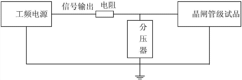
[0053] Such as figure 2 As shown, the short-circuit test mainly detects whether the thyristors in the thyristor-level unit are short-circuited or open-circuited. The short-circuit test of the thyristor-level unit uses an AC power supply with a frequency of 50 Hz (set by a high-voltage sinusoidal excitation with a variable frequency), and applies a power frequency voltage with a peak voltage of about 350 V. The peak voltage across the thyristor is detected by the voltage divider, and compared with the set voltage threshold, if it is higher than the minimum voltage, the experiment is passed. At the same time, the current flowing through the thyristor is detected to judge whether it exceeds the set current threshold. If it does not exceed, it means that there is an open circuit, and the experiment fails. The voltage divider here is one of the measuring devices of the distributed measurement unit, and the voltage divider is arranged in parallel at both ends of each thyristor sta...
PUM
 Abstract
Description
Claims
Application Information