Method and apparatus for drawing a mass of melt-spun fiber slivers

A fiber and sliver technology, applied in the direction of stretch spinning, melt spinning, and complete sets of equipment for the production of artificial threads, etc., can solve the problems of insufficient shaping of the thin neck point, winding, and shifting of the thin neck point

Active Publication Date: 2021-01-08
OERLIKON TEXTILE GMBH & CO KG
View PDF9 Cites 0 Cited by
  • Summary
  • Abstract
  • Description
  • Claims
  • Application Information

AI Technical Summary

Problems solved by technology

But this neck point setting is completely insufficient and can lead to so-called neck point shifts
In particular, the movement of the neck point within the fiber onto the roll surface of one of the draw rolls causes filament breakage, which often results in coiling

Method used


Image

  • Method and apparatus for drawing a mass of melt-spun fiber slivers
  • Method and apparatus for drawing a mass of melt-spun fiber slivers
  • Method and apparatus for drawing a mass of melt-spun fiber slivers

Examples


Embodiment Construction

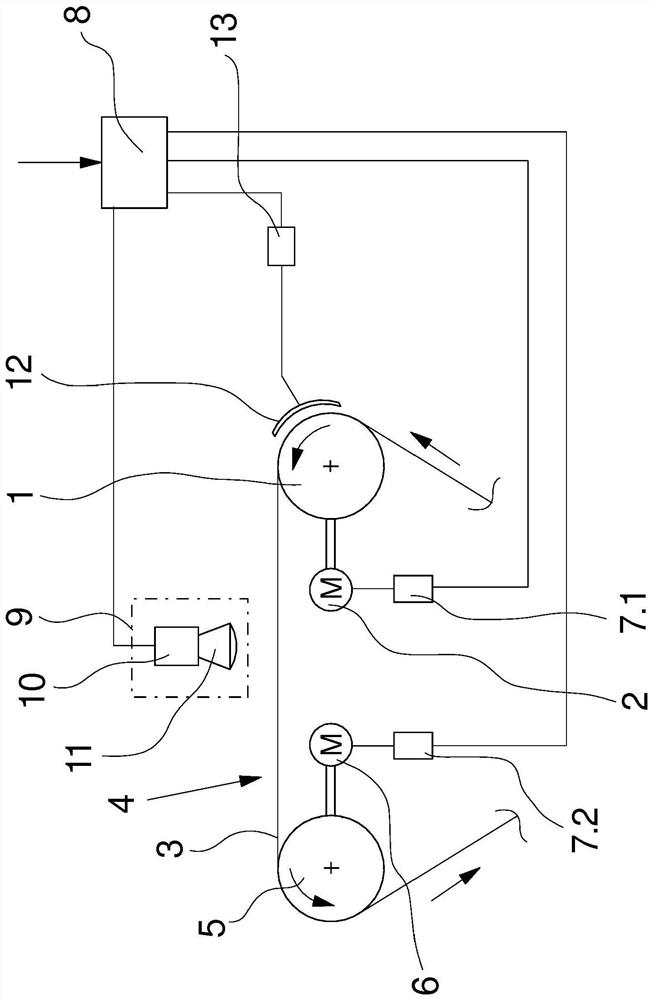
[0040] figure 1 A first embodiment of an apparatus for drawing a mass of melt-spun fiber slivers of tow is schematically shown in . The exemplary embodiment has here only the essential parts of the device required to explain the invention. To this end, a first stretching roller 1 is shown, which is connected to a roller drive 2 . The roll drive 2 is controlled by the drive controller 7.1 in such a way that the stretching roll 1 can be driven with a selectable surface speed / circumferential speed.

[0041] The second stretching roll 5 is assigned to the first stretching roll 1 and is spaced therefrom. A drawing zone 4 is defined between the drawing rolls 1 and 5 in which the tow 3 is drawn. The stretching rollers 5 are driven by a roller drive 6, which is connected to a drive controller 7.2. The drive controller 7 . 2 is connected to the control device 8 , which is likewise connected to the drive controller 7 . 1 of the roller drive 2 of the first stretching roller 1 . A di...


PUM


Abstract

The invention relates to a method and an apparatus for drawing a multiplicity of melt-spun fibre strands of a fibre tow. The fibre tow is guided, at least in a drawing zone, between two drawing rollers and is drawn as a result of a differential speed of the drawing rollers. This results in the formation, within the drawing zone, of a drawing point, which is defined by at least one process parameter being set. In order to monitor and correct the position of the drawing point, a surface temperature of the fibre strands of the fibre tow is measured within the drawing zone, and the setting of the process parameter is adapted in dependence on an actual value of the surface temperature. For this purpose, the drawing zone is assigned a measuring device for measuring a surface temperature of the fibre strands, said measuring device being coupled to the control device and / or a control unit.

Description

technical field [0001] The invention relates to a method for drawing a mass of melt-spun fiber slivers of tow and an apparatus for drawing a mass of melt-spun fiber slivers of tow. Background technique [0002] During the production of staple fibers, a large number of fine fiber strands are usually formed from a polymer melt by extrusion, cooling and overall processing in several stages. In this case, the physical properties of the fibers, such as the strength, are determined primarily by the drawing of the fibers. To achieve the drawing, the fiber sliver is guided as a ribbon-like tow by drawing rollers as a whole. In a stretching zone defined by at least two stretching rolls running at differential speeds, the fiber sliver is subjected to tension and elongated. This process is basically determined by the set differential speed of the draw rolls and the thermal state of the fibers. The degree of uniformity of stretching is manifested by the position of so-called neck-poi...

Claims


Application Information

Patent Timeline
Patent Type & Authority Patents(China)
IPC IPC(8): D01D5/16D01D5/26D01D5/08D02J1/22D01D10/02D01D13/00
CPCD01D5/08D01D5/16D01D5/26D01D10/02D01D13/00D02J1/224D01D5/12
Inventor W-M·卡尔森-布拉克
Owner OERLIKON TEXTILE GMBH & CO KG
Why Eureka
Try Eureka