

Method and coating system for coating cavity walls
A technology for coating and chamber walls, applied in the field of coating chamber walls and coating systems
Active Publication Date: 2017-09-26
STURM MASCH & ANLAGENBAU GMBH
View PDF9 Cites 1 Cited by
- Summary
- Abstract
- Description
- Claims
- Application Information
AI Technical Summary
Problems solved by technology
[0007] A disadvantage of the known coating systems is that, in many cases, the actual dimensions of the cavities coated have an undesirably high deviation from the target value, which deviations can at best be determined in tests, but not be avoided
Method used
View moreImage
Smart ImageViewing Examples

Examples
Embodiment Construction
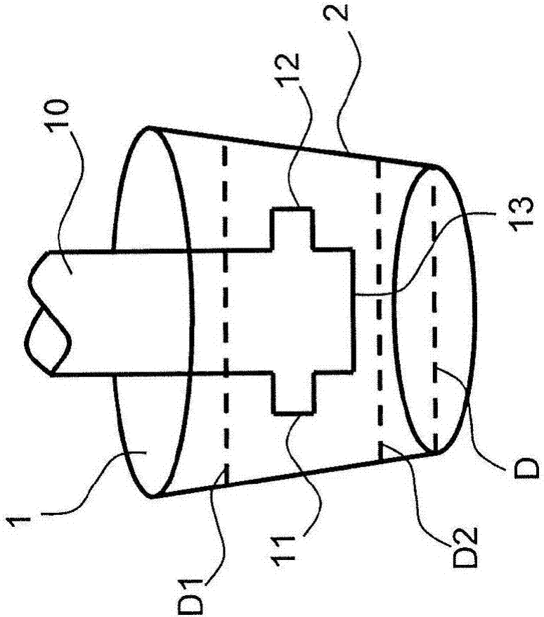
[0047] figure 1 A measuring device 10 of one embodiment of the coating system according to the invention is shown schematically. The measuring device 10 has been moved into the cavity 1 which may in particular be the cylinder bore 1 of the engine block.
[0048] The side walls 2 of the cavity are to be coated, whereby desired wall properties can be obtained, for example to increase the efficiency of the engine.
[0049] The side walls 2 are formed by the side surfaces of the cavity 1, here also referred to simply as "wall 2".
Login to View More PUM
 Abstract
The invention relates to a method for coating cavity walls, in particular cylinder bores of engine blocks. In the method, a coating is applied to a cavity wall using a coating lance. In addition, a cavity diameter is measured using a measuring apparatus. According to the invention, the method is characterized in that at least a plurality of diameter values of a first cavity are measured at different heights of the first cavity using the measuring apparatus, and in that a coating of variable thickness is applied to a wall of the first or a second cavity using the coating lance, the thickness of said coating of variable thickness being dependent on the determined diameter values. The invention additionally describes a corresponding coating system.
Description
technical field [0001] In a first aspect, the invention relates to a method for coating a cavity wall, in particular a cylinder bore of an engine block, according to the preamble of claim 1 . [0002] In a second aspect, the invention relates to a coating system for coating a cavity wall, in particular a cylinder bore of an engine block, according to the preamble of claim 11 . Background technique [0003] Engine blocks of this type are used, for example, in internal combustion engines of motor vehicles. It consists of a number of cylinder bores whose dimensions and wall characteristics meet precise requirements to ensure that the combustion engine is as efficient as possible. In this case, a cylinder bore can generally be understood as a cylindrical cavity with an arcuate, especially circular cross-section. A coating is provided on the inner wall of the cylinder bore, which coating needs to comply with the requirements for its layer thickness with the highest possible pre...
Claims
Login to View More Application Information
Patent Timeline
 Patent Type & AuthorityApplications(China)
IPC IPC(8): G01B21/14G01B5/00G01B11/06G01B11/12C23C4/134
CPCC23C4/134G01B5/003G01B11/0683G01B11/12G01B21/14B05B12/084B05B7/226B05B13/0636B05D1/08B05D1/02B05D7/22
Inventor帕特里克·维默尔法比安·伯尔尼温克勤马克·凯斯廷拉尔夫·沃尔英格沃尔夫冈·舒茨
OwnerSTURM MASCH & ANLAGENBAU GMBH