Supercharge Your Innovation With Domain-Expert AI Agents!

Model coil spring device and control method for same

A technology of coil springs, control methods, applied in the direction of springs, measuring devices, springs/shock absorbers, etc.

Active Publication Date: 2017-09-26
NHK SPRING CO LTD
View PDF6 Cites 0 Cited by
  • Summary
  • Abstract
  • Description
  • Claims
  • Application Information

AI Technical Summary

Problems solved by technology

Although the upper bearing is arranged between the upper spring base and the fixed frame on the side of the vehicle body, the upper bearing has a certain degree of friction (rotational resistance)

Method used


Image

  • Model coil spring device and control method for same
  • Model coil spring device and control method for same
  • Model coil spring device and control method for same

Examples


Embodiment Construction

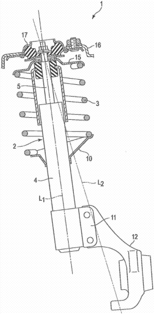
[0026] figure 1 A suspension device for a vehicle is shown, which is a MacPherson strut type suspension device 1 . The suspension device 1 includes a shock absorber serving as a strut 2, and a coil spring 3 for suspension (hereinafter simply referred to as a coil spring 3). The strut 2 includes an outer cylinder 4 as a first strut element 1 and a rod 5 as a second strut element. A rod 5 is inserted into the outer cylinder 4 . The rod 5 inserted into the outer cylinder 4 has a shock-absorbing structure. The outer cylinder 4 and the rod 5 are mutually along the L 1 The direction of the axis (strut axis) moves.

[0027] The outer cylinder 4 is disposed on the lower spring base 10 . The lower end of the outer cylinder 4 is placed on the bracket 11 . A joint material 12 is attached to the bracket 11 . The vehicle axle is supported by the joint material 12 . The upper end of the rod 5 is provided with an upper spring base 15 . A fixed insulator 17 is disposed between the up...


PUM


Abstract

A model coil spring device (20) that is provided with: a first attachment member (21) that is arranged on a lower-side spring seat (10A); a second attachment member (22) that is arranged on an upper-side spring seat (15A); an actuator unit (30) that comprises a Stewart-platform-type parallel mechanism; a hydraulic pressure supply device (37); a torsion detection mechanism (40A); and a control unit (70). The torsion detection mechanism (40A) is configured from displacement gauges (401-406) such as linear variable differential transformers (LVDTs). The displacement gauges (401-406) are provided to respective hydraulic cylinders (311-316) and detect the amount that each of the hydraulic cylinders (311-316) is displaced from a reference length. On the basis of the detected displacement amounts, the control unit (70) calculates the relative torsion angle between the first attachment member (21) and the second attachment member (22).

Description

technical field [0001] The present invention relates to a pseudo coil spring capable of generating a reaction force, such as a coil spring for a suspension, and a control method thereof. Background technique [0002] One type of suspension device for a vehicle is a MacPherson strut type suspension device. The MacPherson strut type suspension device has a coil spring and a strut (shock absorber) arranged inside the coil spring. Applying pressure above the coil spring compresses the coil spring, and the coil spring shrinks accordingly according to the load, and at the same time the strut also shrinks. [0003] In the MacPherson strut type suspension, in order to reduce the sliding resistance of the strut, the position of the reaction force line of the coil spring deviates from the center of the coil spring. For example, the reaction force line is arranged at the position where the friction of the strut is the least. Therefore, it is necessary to know the relationship betwee...

Claims


Application Information

Patent Timeline
Patent Type & Authority Applications(China)
IPC IPC(8): G01L5/16G01L5/00B60G15/06
CPCG09B23/08G09B25/025G01L3/00F16F1/04F16F2230/0017
Inventor 仲村崇广古川和夫森山千里佐藤隆一西泽真一
Owner NHK SPRING CO LTD
Features
  • R&D
  • Intellectual Property
  • Life Sciences
  • Materials
  • Tech Scout
  • Unparalleled Data Quality
  • Higher Quality Content
  • 60% Fewer Hallucinations
Learn More