Full wave dipole array having improved squint performance

A technology of arrays and radiating elements, applied in the field of full-wave dipole arrays with improved skew performance, capable of solving problems such as skew degradation, unfavorable coupling of full-wave dipole arrays, and cross-polarization

Inactive Publication Date: 2017-09-26
COMMSCOPE TECH LLC
View PDF7 Cites 5 Cited by
  • Summary
  • Abstract
  • Description
  • Claims
  • Application Information

AI Technical Summary

Problems solved by technology

[0005] While full-wave dipoles have certain advantages in arrays of low-band radiating elements in multi-band arrays, known full-wave dipole arrays typically suffer from a split between two adjacent -45 degree po

Method used


Image

  • Full wave dipole array having improved squint performance
  • Full wave dipole array having improved squint performance
  • Full wave dipole array having improved squint performance

Examples


Embodiment Construction

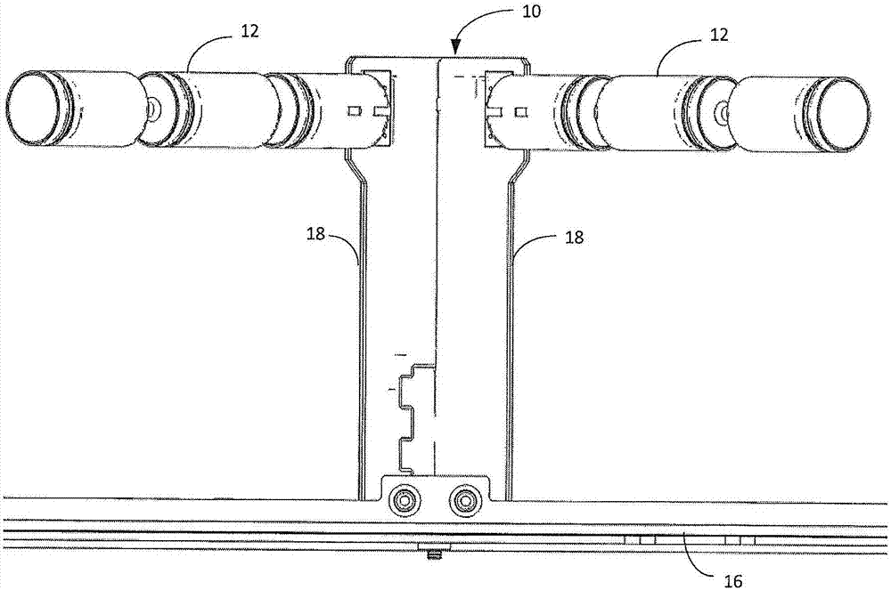
[0021] Figure 1a One example of a microstrip supporting PCB radiating element 10 is shown. Microstrip Supported PCB Radiating Element 10 includes a low frequency band dipole arm 12 supported above reflector 16 by a microstrip supported PCB 18 . In the example shown, the low-band dipole arm 12 includes a full-wave dipole spanning from approximately three-quarters of a wavelength to one full wavelength of the operating frequency band of the microstrip-supported PCB radiating element 10 . Optionally, the low-band dipole arms 12 include RF chokes that resonate at high-band frequencies to minimize scattering from high-band components. See, eg, International Patent Publication No. WO 2014100938 ("the '938 application"), which is incorporated by reference.

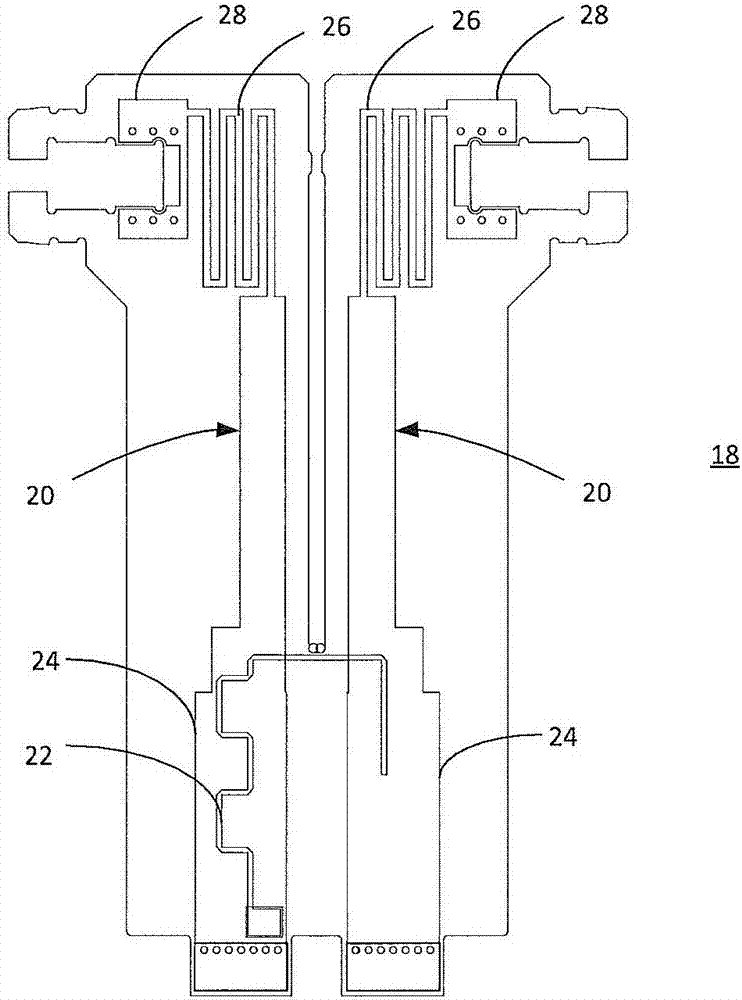
[0022] In the microstrip supported PCB radiating element 10, the low frequency band dipole arm 12 is supported by the microstrip supported PCB 18 ( Figure 1b )excitation. As used herein, the term "microstrip" has its conven...


PUM


Abstract

A cellular base station antenna having improves squint performance is provided. The antenna includes a ground plane, a first plurality of radiating elements supported over the ground plane by microstrip support PCBs, and a second plurality of radiating elements supported over the ground plane by stripline support PCBs. The first and second pluralities of radiating elements are arranged in at least one array of low band radiating elements, and the quantities of first and second pluralities of radiating elements are selected to reduce squint of a beam produced by the at least one array. The first plurality of radiating elements may be located below the second plurality of radiating elements in the array. The array may be arranged in a linear column or a staggered column. In one example, the first plurality of radiating elements comprises four radiating elements and the second plurality radiating elements comprises two radiating elements.

Description

[0001] Related application statement [0002] This application claims priority to US Provisional Patent Application Serial No. 62 / 120,689, filed February 25, 2015, the disclosure of which is incorporated by reference. technical field [0003] The invention relates to an antenna comprising an array of radiating elements. In particular, the present invention provides improved squint performance for arrays of radiating elements. Background technique [0004] Arrays of full-wave dipole radiating elements have been observed to suffer from deflection at high electrical downtilt angles. The term "skew" refers to the amount by which the beam peak (midpoint between -3dB angles) deviates from the antenna boresight. see for example Figure 9 , which illustrates an azimuth beam pattern with a skew of about 12°. A "full wave" dipole radiating element is a type of dipole designed such that its second resonant frequency is in the desired frequency band. In this type of dipole, the dipo...

Claims


Application Information

Patent Timeline
IPC IPC(8): H01Q1/24H01Q5/40H01Q9/18H01Q21/00H01Q21/06H01Q21/08
CPCH01Q1/246H01Q5/40H01Q9/18H01Q21/0075H01Q21/0081H01Q21/062H01Q21/08
Inventor P·J·必思鲁勒斯A·殊施塔瑞
Owner COMMSCOPE TECH LLC
Why Eureka
Try Eureka