Screwdrivers for use with impact drivers

A driving device and driver technology, applied in the direction of power tools, manufacturing tools, etc., can solve problems such as damage to the edge of the handle and can no longer be held

Active Publication Date: 2019-09-03
吴昆霖
View PDF1 Cites 0 Cited by
  • Summary
  • Abstract
  • Description
  • Claims
  • Application Information

AI Technical Summary

Problems solved by technology

[0003] However, the oscillating effect of the screwdriver with the impact driver can cause the round bearing of the screwdriver to break the shank edge of the bit it holds in the driven position
When this happens, the bearing can no longer grip the shank of the bit and cannot turn freely in the drive position

Method used


Image

  • Screwdrivers for use with impact drivers
  • Screwdrivers for use with impact drivers
  • Screwdrivers for use with impact drivers

Examples


Embodiment Construction

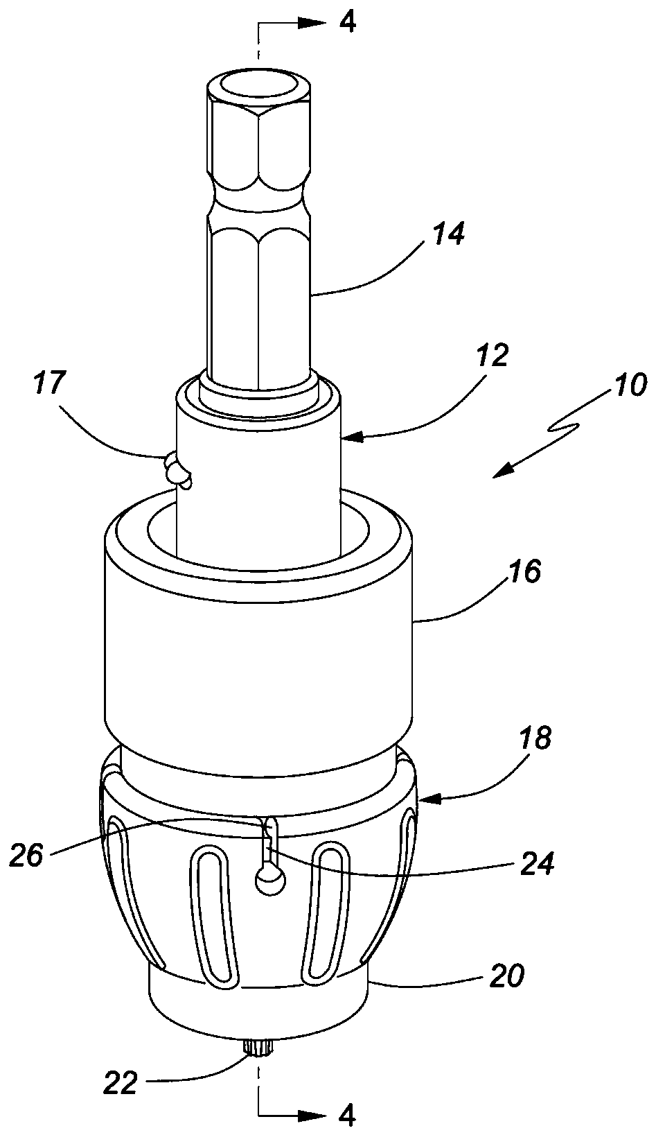
[0017] figure 1 is a perspective view of a screw driving device 10 according to the present invention.

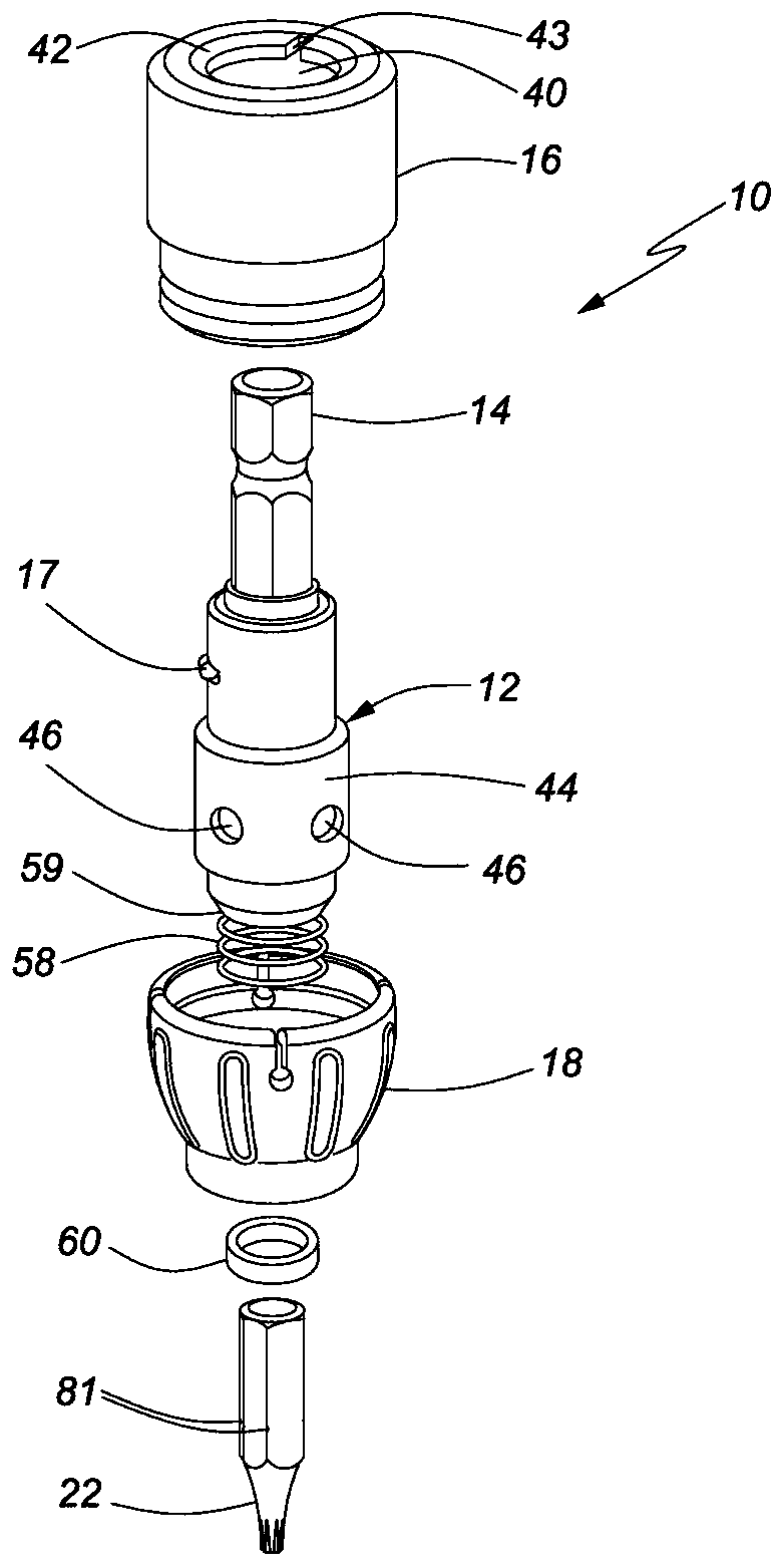
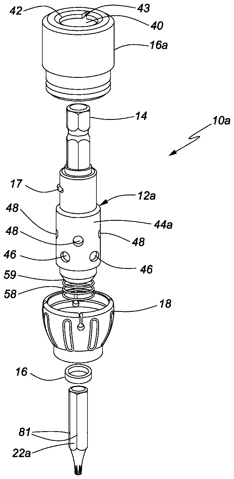
[0018] The screw driver 10 has a drive shaft 12 having a drive end 14 adapted to be engaged and driven by a hand-held electric impact driver (not shown); such hand-held power tools are well known in the art.

[0019] A hollow clutch sleeve 16 accommodates the drive shaft 12; a locking protrusion 17 is formed on the side of the drive shaft 12 to lock the screw driver 10 in a locked position for removing the driven screw.

[0020] The following reference Figure 9 Illustrated, a depth control sleeve (nose cone) 18 grips the bottom end of the hollow clutch sleeve 16, the depth control sleeve 18 having a bottom 20 through which a bit 22 is received at the bottom end of the drive shaft 12 .

[0021] The following reference Figure 4 to Figure 8 Illustrating, the bit 22 rotates with the drive shaft 12 when the screw driver 10 is in the drive position, and the bit 22 is releas...


PUM


Abstract

The invention discloses a screw driving device used with an impact driver together. The screw driving device comprises a driving shaft, a hollow clutch sleeve, a depth control sleeve and a spring. The driving shaft is provided with a driving end and an inserting seat end provided with an annular wall; the annular wall is provided with a plurality of radial holes, clutch bearings are retained in the radial holes correspondingly, and the clutch bearings are cylinders with the head cutting conical ends; the hollow clutch sleeve is provided with a top end, a bottom end and a center channel; the top end of the center channel allows passing through of the driving end but does not allow passing through of the inserting seat end; an annular groove is formed in the position, at the bottom end of the center channel, of the hollow clutch sleeve; the annular groove is suitable for containing the corresponding clutch bearing when the driving shaft is located in the clutch position to enable the head cutting conical end of the clutch bearing to be separated from a screwdriver head to be kept in the corresponding radial hole; the depth control sleeve is located around the bottom end of the hollow clutch sleeve and provided with a bottom, and the bottom is provided with a first channel for allowing extending and passing through of the screwdriver head; and the spring is used for pushing the driving shaft to the driving position.

Description

technical field [0001] The invention relates to a screw driving device, in particular to a screw driving device used in an impact driver to control the depth of a screw being driven into a workpiece. Background technique [0002] Conventional arrangements for driving screws using power tools such as electric drills or impact drivers are well known in the art. For example, the "power transmission type screw screw in and out dual-purpose automatic stopper" disclosed in Taiwan No. 098218832 patent can work very well for electric drill drives that provide smooth and continuous driving force. However, due to the current use of longer and longer screws (screws) in the construction industry, electric drills are not efficient in driving these screws. Therefore, screw drives with impact drivers are used for driving long screws. The impact driver provides the oscillating torque needed to drive long screws, while the screwdriver controls the depth of screw penetration into the workpi...

Claims


Application Information

Patent Timeline
Patent Type & Authority Patents(China)
IPC IPC(8): B25B21/02
Inventor 吴昆霖
Owner 吴昆霖
Why Eureka
Try Eureka