Rapid deoiling device for rare earth feed liquid

A rare earth material liquid, fast technology, applied in the direction of process efficiency improvement, etc., can solve the problem of rare earth material liquid degreasing, etc., to achieve the effect of complete degreasing and precise rotation

Active Publication Date: 2017-09-29
徐玉玉
View PDF5 Cites 8 Cited by
  • Summary
  • Abstract
  • Description
  • Claims
  • Application Information

AI Technical Summary

Problems solved by technology

[0005] In order to overcome the disadvantage that the existing oil removal device for rare earth material liquid usually adopts the traditional structure and cannot quickly degrease the rare earth material liquid, the technical problem to be solved by the present invention is to provide a rare earth material liquid Liquid quick degreasing device

Method used


Image

  • Rapid deoiling device for rare earth feed liquid
  • Rapid deoiling device for rare earth feed liquid
  • Rapid deoiling device for rare earth feed liquid

Examples


Embodiment 1

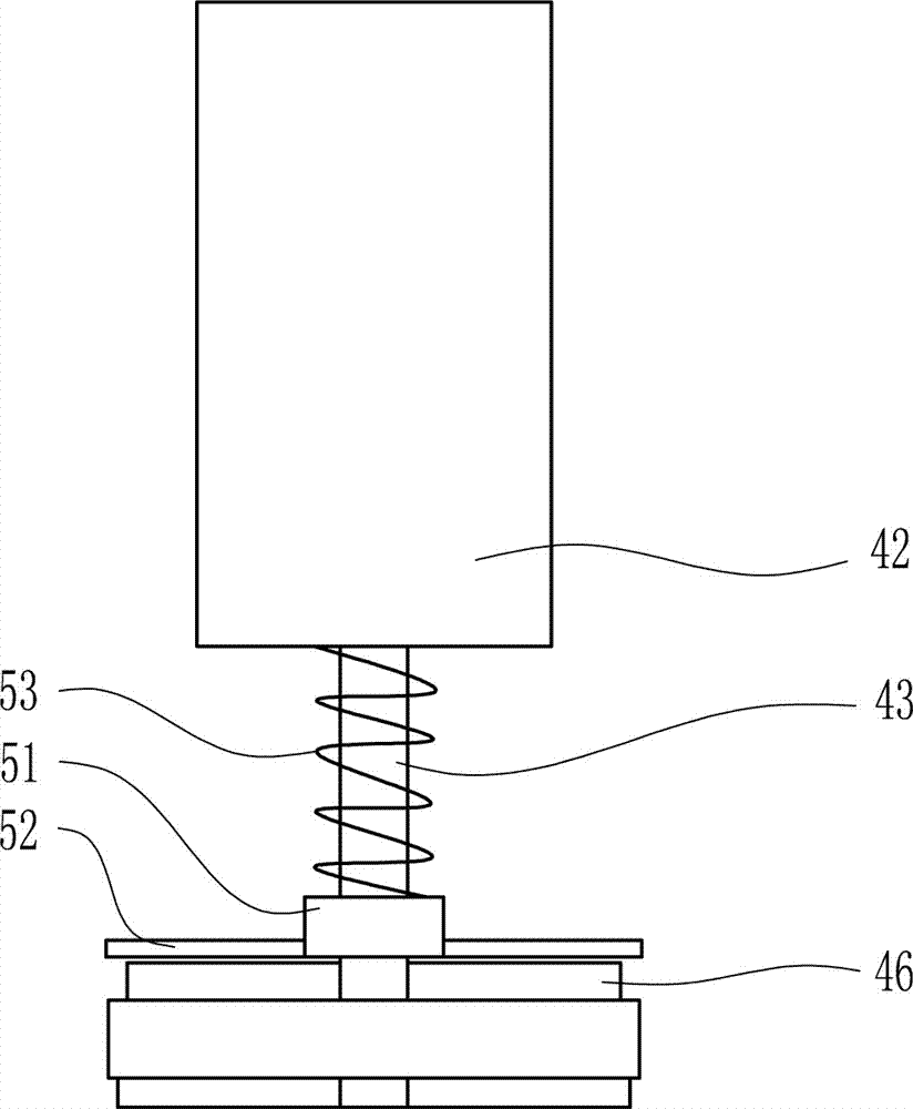
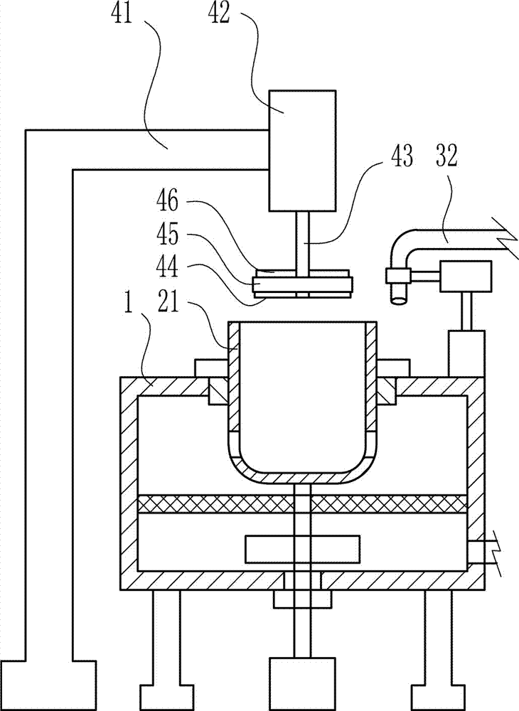
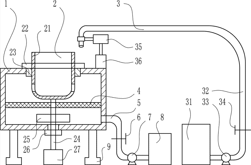
[0028] A quick degreasing device for rare earth feed liquid, such as Figure 1-4 As shown, it includes oil removal tank 1, rotating device 2, material receiving device 3, filter cloth 4, connecting pipe 5, valve I6, high pressure pump I7, material storage tank 8 and legs 9; the middle part of the top of oil removal tank 1 There is an opening, the rotating device 2 is installed on the oil removal tank 1, the material receiving liquid device 3 is arranged on the right side of the oil removal tank 1, the filter cloth 4 and the lower part of the inner wall of the oil removal tank 1 are connected by screws, and the right side of the oil removal tank 1 The lower part of the side wall is connected to the left end of the connecting pipe 5 by welding, the connecting pipe 5 communicates with the oil removal tank 1, and the connecting pipe 5 is equipped with a valve I6 and a high-pressure pump I7, and the high-pressure pump I7 is set on the right side of the valve I6. The right end of th...

Embodiment 2

[0030] A quick degreasing device for rare earth feed liquid, such as Figure 1-4 As shown, it includes oil removal tank 1, rotating device 2, material receiving device 3, filter cloth 4, connecting pipe 5, valve I6, high pressure pump I7, material storage tank 8 and legs 9; the middle part of the top of oil removal tank 1 There is an opening, the rotating device 2 is installed on the oil removal tank 1, the material receiving liquid device 3 is arranged on the right side of the oil removal tank 1, the filter cloth 4 and the lower part of the inner wall of the oil removal tank 1 are connected by screws, and the right side of the oil removal tank 1 The lower part of the side wall is connected to the left end of the connecting pipe 5 by welding, the connecting pipe 5 communicates with the oil removal tank 1, and the connecting pipe 5 is equipped with a valve I6 and a high-pressure pump I7, and the high-pressure pump I7 is set on the right side of the valve I6. The right end of th...

Embodiment 3

[0033] A quick degreasing device for rare earth feed liquid, such as Figure 1-4 As shown, it includes oil removal tank 1, rotating device 2, material receiving device 3, filter cloth 4, connecting pipe 5, valve I6, high pressure pump I7, material storage tank 8 and legs 9; the middle part of the top of oil removal tank 1 There is an opening, the rotating device 2 is installed on the oil removal tank 1, the material receiving liquid device 3 is arranged on the right side of the oil removal tank 1, the filter cloth 4 and the lower part of the inner wall of the oil removal tank 1 are connected by screws, and the right side of the oil removal tank 1 The lower part of the side wall is connected to the left end of the connecting pipe 5 by welding, the connecting pipe 5 communicates with the oil removal tank 1, and the connecting pipe 5 is equipped with a valve I6 and a high-pressure pump I7, and the high-pressure pump I7 is set on the right side of the valve I6. The right end of th...


PUM


Abstract

The invention relates to a deoiling device, in particular to a rapid deoiling device for rare earth feed liquid. The rapid deoiling device for rare earth feed liquid for solving technical problems comprises a deoiling box, a rotating device, a feed liquid collection device, a filter cloth, a connection pipe, a first valve and the like. The rotating device is installed on the deoiling box, the feed liquid collection device is arranged on the right side of the deoiling box, the filter cloth is in screw connection with the lower portion of the inner side wall of the deoiling box, the lower portion of the right side wall of the deoiling box is in welded connection with the left end of the connection pipe, and the connection pipe communicates with the deoiling box. According to the rapid deoiling device for rare earth feed liquid, by combining the filter cloth, the rotating device and the feed liquid collection device, rare earth feed liquid can be rapidly deoiled.

Description

technical field [0001] The invention relates to an oil removal device, in particular to a rapid oil removal device for rare earth feed liquid. Background technique [0002] Rare earths are integral to the manufacture of everything from precision-guided weapons known as "smart bombs" to radar and night-vision goggles. Because of its low natural abundance and the symbiotic form of oxides or oxo-salt minerals, it is called "rare earth". The term rare earth is a name left over from history. Rare earth elements have been discovered since the end of the 18th century. At that time, people often called the solid oxides insoluble in water as soil. Rare earths are generally separated in the form of oxides. Although the reserves on the earth are very large, it is difficult to smelt and purify them, so they are relatively rare, so they are named rare earths. Generally speaking, rare earths on earth exist in the form of rare earth oxides. Rare earth element oxides refer to oxides of ...

Claims


Application Information

Patent Timeline
Patent Type & Authority Applications(China)
IPC IPC(8): C22B59/00C22B3/22
CPCC22B3/22C22B59/00Y02P10/20
Inventor 不公告发明人
Owner 徐玉玉
Why Eureka
Try Eureka