
A roving pull-type controllable feeding spinning device

A drawing type, roving technology, applied in the field of spinning, can solve the problems of poor evenness of yarn, inability to adjust the main draft freely, and low cost of transformation, and achieves increased variety, convenient and controllable feeding, improved The effect of yarn comprehensive quality

Active Publication Date: 2019-03-01
新疆天棉基业纺织有限公司
View PDF5 Cites 0 Cited by
  • Summary
  • Abstract
  • Description
  • Claims
  • Application Information

AI Technical Summary

Problems solved by technology

The modification cost of this method is lower and the efficiency is higher, but the evenness of yarn dryness is poor
In view of this, in the Chinese patent "Segment Color Spinning Transmission Device (Patent No.: ZL200420081737.2)", a segment color yarn production device with four loops is provided, but this device still uses double roving feeding, and at the same time , the first roller and the second roller are still controlled by the same motor, so the main draft cannot be adjusted freely

Method used


Image

  • A roving pull-type controllable feeding spinning device

Examples


Embodiment Construction

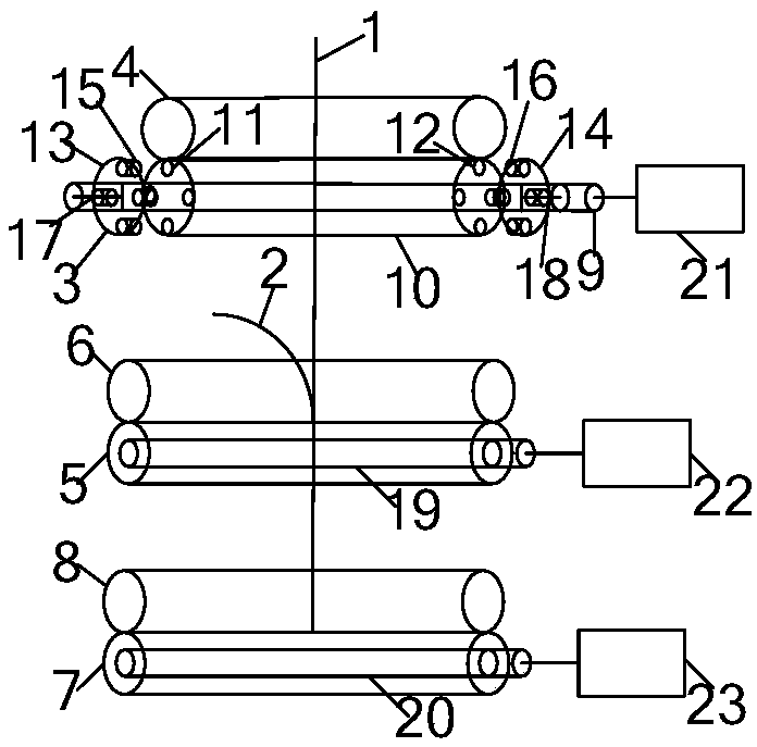
[0009] Depend on figure 1 As shown, a roving pull-type controllable feeding spinning device includes a rear draft roller pair composed of a rear roller 3 and a rear rubber roller 4, and a middle draft roller composed of a middle roller 5 and a middle rubber roller 6. Pair, the front drafting roller pair consisting of the front roller 7 and the front rubber roller 8, the middle roller includes the middle roller shaft 19, the middle roller shaft is a solid cylinder, and the middle roller sleeve is fixedly connected to the middle roller shaft, and the front roller Including the front roller shaft 20, the front roller shaft is a solid cylinder, the front roller shaft is fixedly connected with a front roller sleeve, the rear roller includes a rear roller shaft 9, the rear roller shaft is a solid cylindrical shape with smooth surface, and the rear roller shaft A back roller cover 10 is installed on the top, and the back roller cover is a steel circular ring with a smooth inner surfa...


PUM


Abstract

The invention relates to a rough yarn pulling-type feeding-controllable spinning device. The rough yarn pulling-type feeding-controllable spinning device comprises a rear roller, a rear rubber roll, a middle roller, a middle rubber roll, a front roller and a front rubber roll. The rear roller comprises a rear roller shaft, and a rear roller sleeve is additionally installed on the rear roller shaft; four left insert holes are arranged in the circular face of the left end of the rear roller sleeve, and four right insert holes are arranged in the circular face of the right end of the rear roller sleeve; the left end stretching out of the rear roller sleeve along the rear roller shaft is provided with a left slideway in the length direction, and the right end stretching out of the rear roller sleeve along the rear roller shaft is provided with a right slideway in the length direction, a left pulling pin is additionally installed in the left slideway, and a right pulling pin is additionally installed in the right slideway; four left insert pins are additionally installed on the outer periphery of the left pulling pin at an equal-arc interval, and four right insert pins are additionally installed on the outer periphery of the right pulling pin at an equal-arc interval a left vertical pin is additionally installed in the center of circle of the left pulling pin, and a right vertical pin is additionally installed in the center of circle of the right pulling pin; and the left vertical pin is connected with the inner side surface of the closed left end of the rear roller shaft through a left telescopic pin, and the right vertical pin is connected with the inner side surface of the closed right end of the rear roller shaft through a right telescopic pin. During the spinning process, interrupted rotation control of the rear roller sleeve is achieved by means of extension and contraction of the left and right telescopic pins, control of interrupted feeding of rough yarns is achieved afterwards, and production of yarns having various fancy effects is achieved.

Description

technical field [0001] The invention relates to the technical field of spinning, in particular to a roving pull-type controllable feeding and spinning device. Background technique [0002] With the continuous advancement of the times, people's requirements for clothing materials continue to increase. At present, the textile and clothing industry is in an era of pursuing fashion, diversification and high quality. Therefore, new requirements have been put forward for the development of textile raw materials, among which fancy yarns have gradually entered people's field of vision and occupy an irreplaceable position. Fancy yarn refers to the yarn with special structure and appearance effect obtained by processing fiber or yarn with special raw materials, special equipment or special technology in the process of spinning and thread making. It is a decorative yarn in yarn products. A kind of yarn that works. Fancy yarn has unique structure, flexible shape, rich color expression...

Claims


Application Information

Patent Timeline
Patent Type & Authority Patents(China)
IPC IPC(8): D01H5/22D01H5/32D01H5/78
CPCD01H5/22D01H5/32D01H5/78
Inventor 刘新金苏旭中
Owner 新疆天棉基业纺织有限公司
Learn More