A transparent soil model test device and test method for simulating soil lateral movement

A model test device and transparent soil technology, which is applied in the test of foundation structure, construction, foundation structure engineering, etc., can solve the problems of low visibility and measurement of pile-soil interaction, achieve small device size, convenient test operation, Reasonable system settings

Active Publication Date: 2020-01-31
重庆大学建筑规划设计研究总院有限公司
View PDF7 Cites 0 Cited by
  • Summary
  • Abstract
  • Description
  • Claims
  • Application Information

AI Technical Summary

Problems solved by technology

[0004] In the prior art, the model test device for simulating the lateral movement of soil can simulate different shapes of displacement loads, analyze the changes in the bearing characteristics of the pile body, and the displacement mode of the soil acting on the surface of the pile body, but it cannot be used for passive piles during the loading process. The development and change of the soil displacement field around the middle pile is measured, and the visualization of the pile-soil interaction is not high

Method used


Image

  • A transparent soil model test device and test method for simulating soil lateral movement
  • A transparent soil model test device and test method for simulating soil lateral movement
  • A transparent soil model test device and test method for simulating soil lateral movement

Examples


Embodiment 1

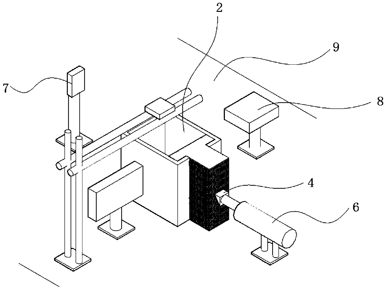
[0037] This embodiment discloses a transparent soil model test device for simulating the lateral displacement of soil, which includes a transparent model box 1 that can be fixed on an optical platform 9, a T-shaped block 3 and a loading block 4.

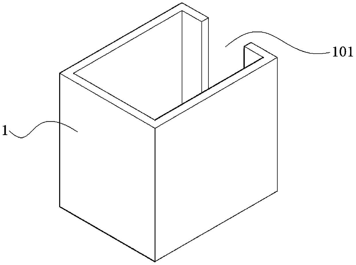
[0038] See figure 1 The transparent model box 1 as a whole is a rectangular box with an open upper end and a hollow inside. There is a rectangular notch 101 on one side of the rectangular box. The transparent model box 1 is made of organic glass.

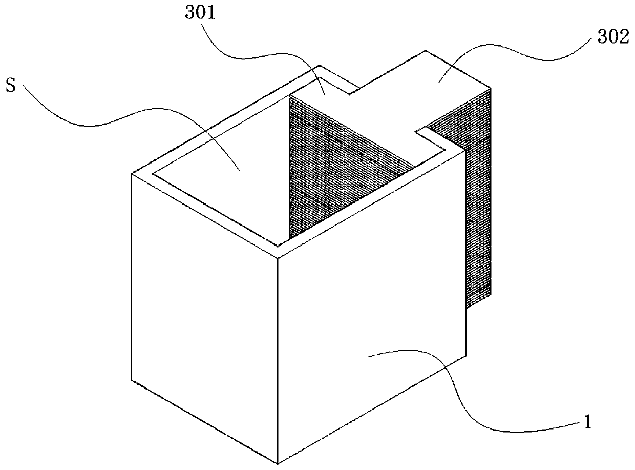
[0039] See Figure 5 versus figure 2 , The cross section of the T-shaped block 3 is T-shaped. The T-shaped block 3 includes a rectangular parallelepiped flange portion 301 and a rectangular parallelepiped web portion 302 that are perpendicular to each other. The T-shaped block 3 is formed by stacking and combining multiple T-shaped sheet-like plates. The T-shaped block 3 is embedded on the notch side of the transparent model box 1. The flange portion 301 is located in the inner cavity of ...

Embodiment 2

[0045] This embodiment discloses a test method related to the above test device, including the following steps:

[0046] 1) Make transparent model box 1, T-shaped sheet plate and loading block 4 according to the designed size, and scrub the side wall of transparent model box 1.

[0047] 2) Stack the T-shaped sheet plates on the notch of the transparent model box 1 to form a T-shaped block 3.

[0048] 3) Place the transparent film bag 5 in the semi-enclosed space S.

[0049] 4) Prepare transparent soil 2 in the transparent film bag 5 to the design height. During the preparation process, the model pile is buried in the design position. After preparation, let it stand for 24 hours. Wherein, the preparation method of the transparent soil 2 is: pour the prepared mixture of white oil and n-dodecane into the transparent film bag 5. The transparent film bag 5 is in close contact with the side wall of the semi-enclosing space S without wrinkles. Then, fused silica sand solid particles with...


PUM


Abstract

The invention provides a transparent soil model test device for simulating lateral soil movement and a test method for the transparent soil model test device. The transparent soil model test device comprises a transparent model box which can be fixed to an optical table, a T-shaped block and a loading block. The whole transparent model box is a rectangular box body. The circumferential wall of one side of the rectangular box body is provided with a rectangular notch. The T-shaped block is embedded in the notch side of the transparent model box. An oil pressure jack, two industrial cameras and two laser transmitters are arranged outside the transparent model box. During testing, a test model pile is buried in transparent soil. The loading block is abutted against a web part by the oil pressure jack. The oil pressure jack applies displacement to the loading block in a graded mode. The two laser transmitters transmit lasers. Two transparent soil speckle fields are formed in the transparent soil. The industrial cameras record the change of the transparent soil speckle fields. The test method for the transparent soil model test device comprises the steps of mold making, transparent soil preparation, graded loading and the like. The transparent soil model test device is small in size, the system is arranged reasonably, and test operation is convenient.

Description

Technical field [0001] The invention relates to the technical field of visual testing of geotechnical engineering, in particular to a transparent soil model test device and a test method for simulating lateral displacement of a soil body. Background technique [0002] With the large-scale development of national construction, a large number of high-rise buildings, bridges and ports continue to emerge, the density of high-speed railways, highways and road networks, the development of urban subway construction, coastal reclamation and large-scale backfilling, the application of passive piles is becoming more and more extensive. It is of great practical significance to study the force and deformation characteristics of passive piles under horizontal lateral displacement. [0003] Traditional passive pile analysis methods include theoretical analysis method and model test method, etc., which are based on the assumed pile-soil relative displacement curve and pile side soil pressure-pile...

Claims


Application Information

Patent Timeline
Patent Type & Authority Patents(China)
IPC IPC(8): E02D33/00
CPCE02D33/00
Inventor 仉文岗周东丁选明向钰周
Owner 重庆大学建筑规划设计研究总院有限公司
Why Eureka
Try Eureka