
Visual measurement method for temperature distribution of annular combustion field

A technology of temperature distribution and measurement method, which is applied in chemical analysis by means of combustion, application of thermometers, thermometers, etc., can solve problems such as increased calculation amount, unconfirmed convergence, and inability to simultaneously give dual-mode distribution information, etc., to achieve Good adaptability and fast response effect

Active Publication Date: 2021-08-10
BEIHANG UNIV
View PDF11 Cites 0 Cited by
  • Summary
  • Abstract
  • Description
  • Claims
  • Application Information

AI Technical Summary

Problems solved by technology

Although image reconstruction methods based on sensitivity matrices have been successfully applied, they also have their own limitations. These methods calculate the gray value of all points in the entire area. If only a small part of the entire area needs to be reconstructed, it will increase many unnecessary Necessary amount of calculation
In addition, the method of iteratively updating the sensitivity matrix is ​​very time-consuming, and the convergence has not been confirmed; at the same time, the sensitivity matrix method cannot simultaneously give the distribution information of the two modes

Method used


Image

  • Visual measurement method for temperature distribution of annular combustion field
  • Visual measurement method for temperature distribution of annular combustion field
  • Visual measurement method for temperature distribution of annular combustion field

Examples


Embodiment Construction

[0073] The invention is a visual measurement method for the temperature distribution of an annular combustion field, and the specific implementation method is as follows:

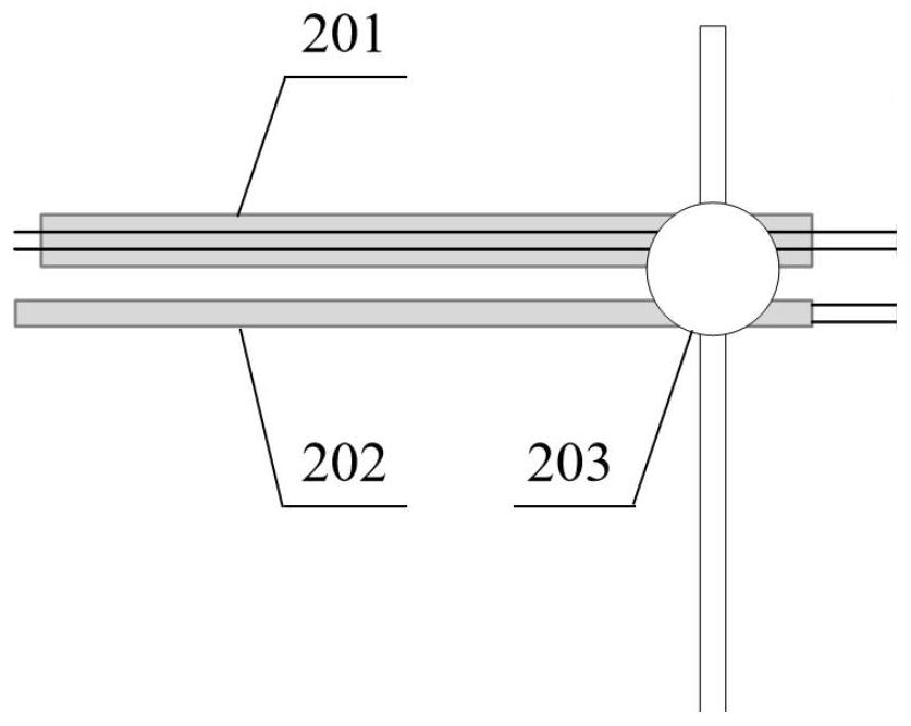
[0074] Step 1: For the typical working conditions of the blunt body turbulent flow burner, increase the intake flow rate of propane fuel from 30mL / min to 50mL / min with a step size of 10mL / min, and increase the intake flow rate of air from 100mL / min To 200mL / min, the step size is 50mL / min, use the ion current probe and thermocouple probe to collect the local admittance and temperature data of the combustion field, such as figure 2 As shown, the ion current probe 201 and the thermocouple probe 202 are connected by a direction-adjustable fixture 203 and fixed on the two-dimensional precision displacement stage, and the impedance of the ion current probe electrode pair is collected by the impedance measurement hardware system connected thereto. The temperature difference caused by the front end of the thermoco...


PUM


Abstract

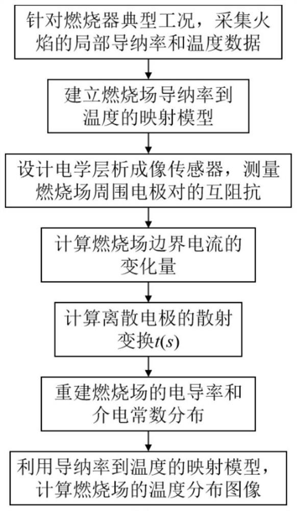
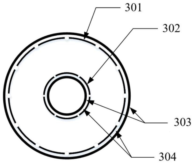
The invention relates to a visual measurement method for temperature distribution of an annular combustion field. The method comprises the following specific operation steps: 1, collecting the local admittance rate and temperature data of a flame through an ionic current probe and a thermocouple probe according to the typical working condition of an annular combustor; 2, establishing a mapping model from the admittance rate of the combustion field to the temperature by using the measured data; 3, according to the structure of the annular combustor, designing an annular electrical tomography sensor, measuring mutual impedance of an electrode array distributed around a combustion field, and reconstructing distribution of conductivity and dielectric constant in the annular combustion field; and 4, substituting the reconstructed distribution data into the mapping model from the admittance rate to the temperature to obtain a temperature distribution image. The method provided by the invention is suitable for measuring the temperature distribution in the combustion field of a combustor with a complex annular structure, does not need an optical window, has the advantages of no contact, no radiation, simple structure, low cost and the like, and has important practical value and application prospect.

Description

technical field [0001] The invention relates to a visual measurement method for the temperature distribution of an annular combustion field, which belongs to the field of dynamic monitoring of the combustion field. Background technique [0002] Combustion is the main form of energy conversion and widely exists in industrial processes. Temperature measurement data can be used to improve combustion process control technology and optimize combustion chamber design to meet energy saving and low emission requirements. Thermocouples and pyrometers are the most commonly used equipment for temperature measurement in combustion fields. However, thermocouples and pyrometers are invasive or contact, and a single measurement can only reflect the local temperature information of the entire combustion field. Passive temperature measurement technology based on flame radiation has achieved certain applications in industrial processes. Active spectral analysis technology based on optical in...

Claims


Application Information

Patent Timeline
IPC IPC(8): G01K11/00G01K13/00G01N31/12
CPCG01K11/00G01K13/00G01N31/12
Inventor 徐立军胡蝶曹章田雨
Owner BEIHANG UNIV
Learn More