Downhole directional hydraulic jetting tool ground control method

A surface control and hydraulic injection technology, which is applied in directional drilling, automatic drilling control system, liquid/gas jet drilling, etc., can solve the problem of lack of accurate downhole orientation ability, inability to realize downhole directional injection, and injection tools cannot be rotated in place and other problems, to achieve the effect of solving limited reservoir transformation, large torque, and avoiding misoperation

Inactive Publication Date: 2017-10-03
BC P INC CHINA NAT PETROLEUM CORP +1
View PDF11 Cites 14 Cited by
  • Summary
  • Abstract
  • Description
  • Claims
  • Application Information

AI Technical Summary

Problems solved by technology

[0004] However, the above-mentioned prior art is easy to get stuck in the underground, and the vibration is large during injection, so that the injection tool cannot be rotated in place or sprayed at one point, which affects the injection effect and cannot meet the construction requirements.
Moreover, at present, the injection holes of hydraulic jet tools at home and abroad are evenly arranged along the circumference of the spray gun, which can only realize the uniform transformation of the reservoir near the injection holes; It is also impossible to realize the requirement of downhole directional injection
Therefore, so far, there is no effective way to achieve reliable directional injection at home and abroad.

Method used


Image

  • Downhole directional hydraulic jetting tool ground control method
  • Downhole directional hydraulic jetting tool ground control method
  • Downhole directional hydraulic jetting tool ground control method

Examples


Embodiment 1

[0039] A method for controlling a downhole directional hydraulic injection tool on the ground, comprising the steps of:

[0040] a. When the downhole directional injection tool reaches the deep position of the injection well, start the downhole directional injection tool through ground control;

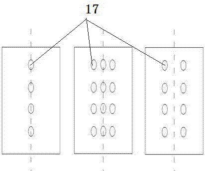
[0041] b. After the downhole directional injection tool is started, identify the circumferential orientation of the injection hole 17 along the wellbore. After determining the initial circumferential orientation of the injection hole 17 in the downhole, compare and analyze it with the set final injection orientation, and obtain that the spray gun 16 needs to rotate direction and angle of

[0042] c. Control the spray gun 16 to rotate according to the required direction and angle, and adjust the orientation of the injection hole 17 along the wellbore circumference to the specified orientation;

[0043]d. When the injection hole 17 on the spray gun 16 is adjusted in place, start direct...

Embodiment 2

[0061] This embodiment further illustrates the present invention in conjunction with the accompanying drawings. Here, the exemplary embodiments and descriptions of the present invention are used to explain the present invention, but not to limit the present invention.

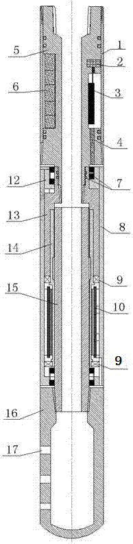
[0062] As shown in the figure, the present invention is mainly divided into two parts: surface control and downhole execution. The ground control part mainly sends start commands to the downhole to ensure that the tool starts to work when needed, which can save battery power to the greatest extent; the downhole part is the downhole directional injection tool, which mainly realizes automatic positioning of spray gun 16 nozzles and along the wellbore circumference. Adjustment.

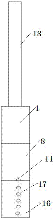
[0063] figure 1 It is a schematic diagram of the downhole tool string of the directional hydrojet tool used for fracturing and acidizing stimulation. The downhole directional injection tool is composed of three parts: a control device,...

Embodiment 3

[0071] After determining the circumferential orientation of the wellbore that the reservoir needs to inject, input the injection orientation data to the downhole directional injection tool on the ground in advance (that is, the injection hole ultimately needs to correspond to the circumferential injection orientation of the wellbore), and set the direction that needs to be injected downhole . When construction is required, the downhole directional injection tool is connected with oil pipe or coiled tubing 18, and sent downhole. When the downhole directional injection tool reaches the deep position of the injection well, the downhole directional injection tool is started by sending a ground control command by throwing an RFID communication ball into the tubing. When the RFID communication ball passes through the downhole directional injection tool with the downhole fluid, the downhole directional injection tool The built-in RFID reader receives the control signal and starts the...


PUM


Abstract

The invention discloses a downhole directional hydraulic jetting tool ground control method. The downhole directional hydraulic jetting tool ground control method comprises that a, when reaching a jetting well depth position, the downhole directional jetting tool is started by means of ground control; b, after the downhole directional jetting tool is started, the circumferential orientation of a jet hole along the borehole is identified, after it is determined that the jet hole is in the downhole initial circumferential orientation, contrastive analysis is carried out on the initial circumferential orientation and a set final jetting orientation, and the direction and angle by which a spray gun needs to rotate are obtained; c, the spray gun is controlled to rotate by the needed direction and angle, the circumferential orientation of the jet hole along the borehole is adjusted to the appointed orientation; and d, after the jet hole in the pray gun is adjusted in place, directional jetted particle perforation is started, and fracture acidizing construction is carried out. According to the invention, the orientation of the jet hole can be adjusted, influence brought by downhole obstructions and spray gun vibrations can be effectively prevented, the directional jetting task can be completed reliably, and interference brought by rotation of the tool during the descending process can be avoided.

Description

technical field [0001] The invention relates to a method for controlling a downhole directional hydraulic injection tool on the ground, which is used for the transformation of horizontal well reservoirs and belongs to the field of well completion transformation used in oil exploitation. Background technique [0002] Water bodies with sufficient energy exist at the bottom of reservoirs in some oilfields in China. In horizontal well reservoir stimulation, how to effectively fracture the reservoir while keeping the bottom water from flowing is an important aspect in process selection and fracturing design. If a horizontal wellbore is drilled in the middle of the reservoir and sandblasting is used in conventional methods, the height of the fracture must be strictly limited in order to avoid communication with the bottom water, which affects the effect of reservoir stimulation, and it is difficult to perform repeated fracturing in the later stage, which limits the The remaining ...

Claims


Application Information

Patent Timeline
Patent Type & Authority Applications(China)
IPC IPC(8): E21B44/02E21B7/04E21B7/18
CPCE21B7/04E21B7/18E21B44/02
Inventor 石磊钟兴久邹先雄曾凌翔潘勇
Owner BC P INC CHINA NAT PETROLEUM CORP
Why Eureka
Try Eureka