Strengthened heat transfer type ternary bending torsion micro convex end face mechanical seal structure

An end face mechanical seal and enhanced heat transfer technology, applied in the direction of engine seals, mechanical equipment, engine components, etc., can solve the problems of high frictional heat generation, weak heat transfer capacity, and poor ability to adapt to solid content media, etc., to improve stiffness and tightness, reduce leakage rate, and improve the effect of sealing ability

Active Publication Date: 2017-10-03
ZHEJIANG UNIV OF TECH
View PDF11 Cites 7 Cited by
  • Summary
  • Abstract
  • Description
  • Claims
  • Application Information

AI Technical Summary

Problems solved by technology

[0004] In order to overcome the shortcomings of the existing contact mechanical seals, which have large frictional heat generation and poor ability to adapt to the environment containing solid particles, and overcome the characteristics of the existing hydrodynamic mechanical seals with weak end surface heat transfer capabilities and poor ability to adapt to s

Method used


Image

  • Strengthened heat transfer type ternary bending torsion micro convex end face mechanical seal structure
  • Strengthened heat transfer type ternary bending torsion micro convex end face mechanical seal structure
  • Strengthened heat transfer type ternary bending torsion micro convex end face mechanical seal structure

Examples


Embodiment 1

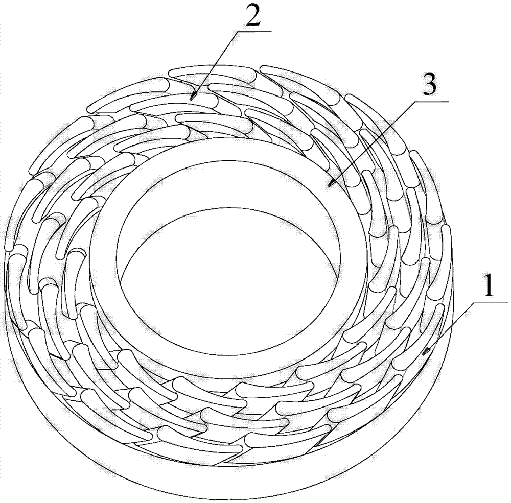
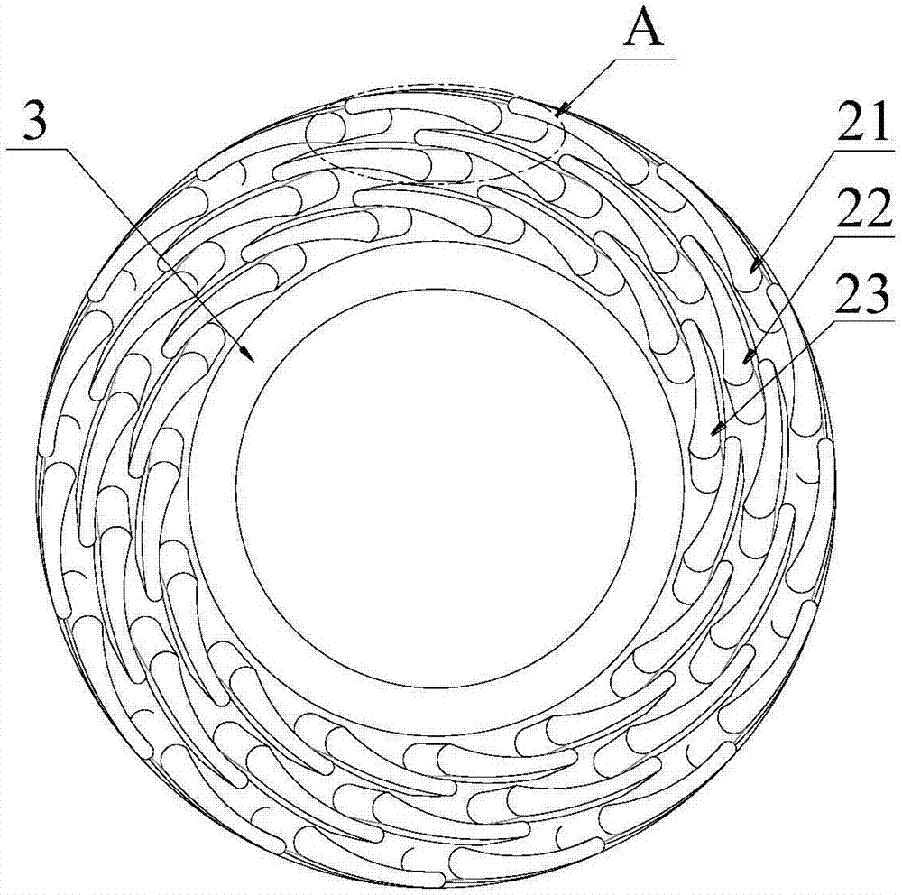
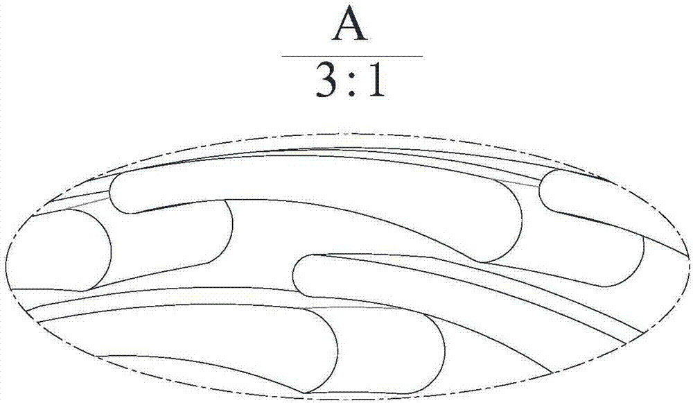
[0028] refer to figure 1 , 2 and 3, 4, 5, a heat transfer-enhanced ternary bending and torsion micro-convex body end face mechanical seal structure, the end faces of the moving ring or the static ring of the mechanical seal are processed along the circumferential direction according to the center of the end face to form an annulus 2 There is a ternary bending and twisting asperity 1, and the ternary bending and twisting asperity 1 is a micro-pillar whose cross-sectional shape is an airfoil, and there is a relative cross section between two adjacent ternary bending and twisting asperities 1 twist, each asperity on the same asperity ring is arranged at the same relative position relative to the center of the end face, which can improve the shear failure resistance of the asperity and improve the wear resistance of the end face ; The major axis of the cross section of the ternary bending and twisting asperity 1 is arranged along the circumferential direction of the end face, the...


PUM

PropertyMeasurementUnit
Maximum radial dimensionsaaaaaaaaaa
Heightaaaaaaaaaa
Surface roughnessaaaaaaaaaa

Abstract

The invention discloses a strengthened heat transfer type ternary bending torsion micro convex end face mechanical seal structure. Ternary bending torsion micro convexes arranged in the circumferential direction according to the center of the end face to form ring belts are machined on the end face of a movable ring or a static ring of a mechanical seal; each ternary bending torsion micro convex is a micro cylinder with the cross section in the wing shape; and relative torsion exists between every two adjacent cross sections on the ternary bending torsion micro convexes. The long axes of the cross sections of the ternary bending torsion micro convexes are arranged in the circumferential direction of the end face; the short axes of the cross sections of the ternary bending torsion micro convexes are arranged in the radial direction of the end face; the end face of the leeward side of the front micro convex on the ring belts is located on the inner side of the end face of the windward side of the back micro convex; a ring direction flow channel is formed between every two adjacent rows of ring belts, and fluid flows into the ring direction flow channels through the micro convexes and generates strong vortex in the ring direction flow channels; every two adjacent rows of ring belts of the ternary bending torsion micro convexes are arranged in a staggered manner; and the position, close to the leakage side, on the sealed end face is provided with an annular sealing dam; and the height of the sealing dam is equal to that of the ternary bending torsion micro convexes.

Description

technical field [0001] The invention relates to a mechanical end face sealing structure of a rotary fluid machine, in particular to a ternary bending and torsion micro-convex body end face mechanical sealing structure, which is used for the shaft end sealing of various compressors, pumps, reaction kettles and other rotating mechanical equipment. , especially suitable for high-speed occasions or occasions requiring high heat transfer performance of the end face, belonging to the technical field of mechanical end face seals. Background technique [0002] Mechanical face seals are widely used in rotating machinery in industries such as petroleum, petrochemical, food, medicine, and papermaking due to their performance advantages such as small leakage, simple structure, and automatic wear compensation. When the traditional ordinary mechanical seal is in operation, the sealing end faces of the dynamic and static rings will have direct contact, and the heat generated by the contact...

Claims


Application Information

Patent Timeline
IPC IPC(8): F16J15/34
CPCF16J15/3408
Inventor 彭旭东江锦波孟祥铠陈源李纪云
Owner ZHEJIANG UNIV OF TECH
Why Eureka
Try Eureka