
Ball valve airtightness test method and test system

An air tightness test, ball valve technology, used in fluid tightness test, liquid/vacuum test for liquid tightness, machine/structural component testing, etc. It can solve problems such as high test costs and save testing. The effect of equipment cost, simple structure, low cost and high test accuracy

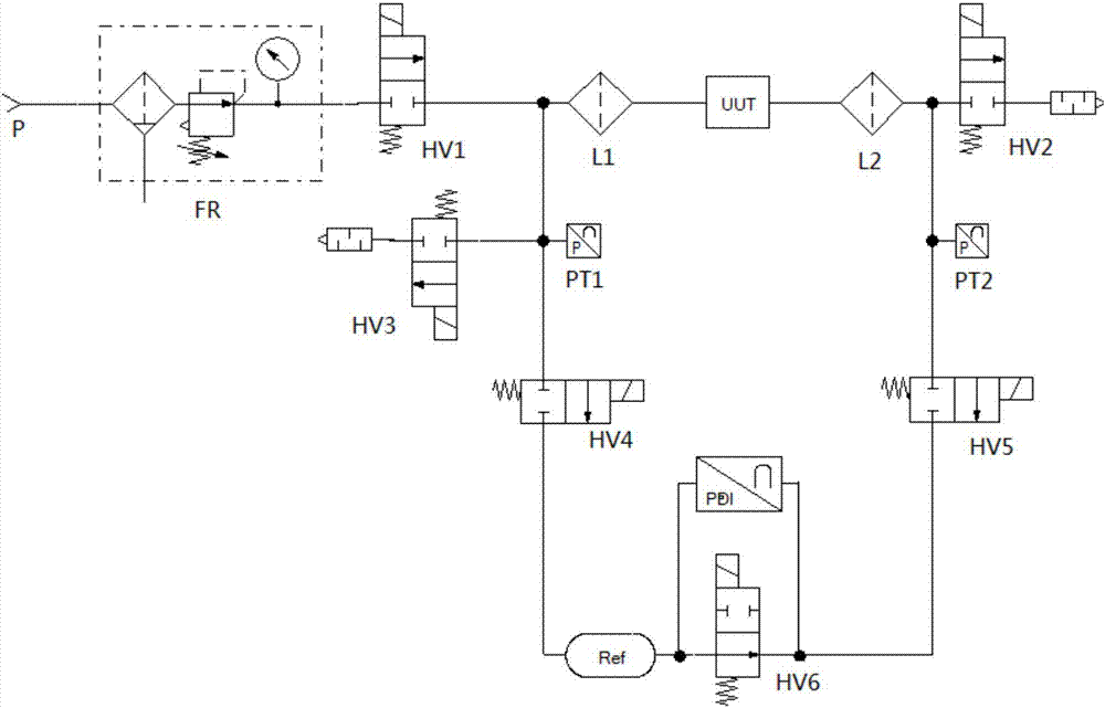
Active Publication Date: 2017-10-03
深圳市高晟智能装备有限公司
View PDF5 Cites 11 Cited by
  • Summary
  • Abstract
  • Description
  • Claims
  • Application Information

AI Technical Summary

Problems solved by technology

[0020] However, this detection system requires two direct pressure sensors and one differential pressure sensor, and the test cost is high.

Method used


Image

  • Ball valve airtightness test method and test system
  • Ball valve airtightness test method and test system

Examples


Embodiment Construction

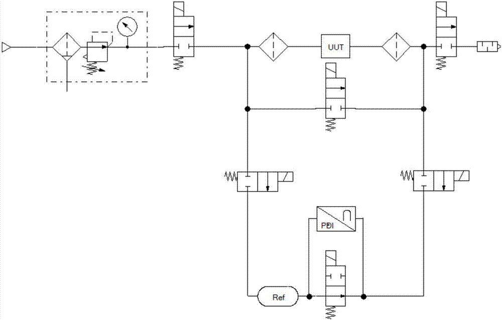
[0043] Such as figure 2 Shown: This embodiment is an automatic test system for external leakage and internal leakage testing of ball valves, including air source P, filter pressure regulating valve FR, inflation valve HV1, filter L, tested ball valve UUT, Filter L, exhaust valve HV2; when inflating, the air source P with a pressure of 0.1-1.2MPa passes through the filter pressure regulating valve FR, the inflation valve HV1, the ball valve UUT under test, the filter L, and is discharged from the exhaust valve HV2. Used here, the filter pressure regulating valve FR and the filter L filter the gas entering the test system to effectively protect the test system. On both sides of the tested ball valve UUT, there is a conduction valve HV3, and the outlet of the charging valve HV1 is connected with a standard chamber Ref. The other outlet is connected to the high pressure end of the differential pressure sensor PDI, and the low pressure end of the differential pressure sensor PDI ...


PUM


Abstract

The present invention discloses a ball valve airtightness test method and test system. According to the test method, an external leakage test and an internal leakage test are performed separately. The system comprises an air source, an inflation valve and an exhaust valve; the inflation valve and the exhaust valve are arranged at two sides of a tested ball valve respectively; a conducting valve is in spanning connection with the two sides of the tested ball valve; one outlet of the inflation valve is connected with a standard cavity; a high-pressure end switching valve is arranged between the inflation valve and the standard cavity; one outlet of the standard cavity is connected with the high-pressure end of a differential pressure sensor; and the low-pressure end of the differential pressure sensor is connected with one side of the tested ball valve through a low-pressure end switching valve, wherein the one side of the tested ball valve is adjacent to the exhaust valve. The test system of the invention has the advantages of simple structure, low cost and high precision of the inner leakage test of the ball valve.

Description

technical field [0001] The invention relates to a ball valve air tightness test method and a test system. Background technique [0002] The ball valve is a valve that uses a sphere with a circular through hole as the opening and closing part, and the sphere rotates with the valve stem to realize the opening and closing action. The ball valve is mainly used to cut off, distribute and change the flow direction of the medium. It needs to be tested for sealing before leaving the factory, otherwise there will be a greater safety hazard during use. [0003] Such as figure 1 Shown is a very typical ball valve air tightness test system. It is a differential pressure + direct pressure comprehensive test method gas circuit. During the test, its related actions are: [0004] Leakage test: the detection part is the shell and the upper seal (the seal of the valve stem) [0005] 1) After the ball valve under test (UUT) is clamped, pull its handle to the 45° position, and the opening a...

Claims


Application Information

Patent Timeline
Patent Type & Authority Applications(China)
IPC IPC(8): G01M3/28
CPCG01M3/2876
Inventor 高炎林崔岩
Owner 深圳市高晟智能装备有限公司
Learn More