
Current carrier and design method thereof

A current carrier and design method technology, applied in the direction of cable/conductor manufacturing, circuit, electrical components, etc., can solve problems such as system reliability deterioration, achieve the effects of improving stability, ensuring electrical connection performance, and good flexibility

Inactive Publication Date: 2017-10-03
NARI TECH CO LTD +1
View PDF5 Cites 1 Cited by
  • Summary
  • Abstract
  • Description
  • Claims
  • Application Information

AI Technical Summary

Problems solved by technology

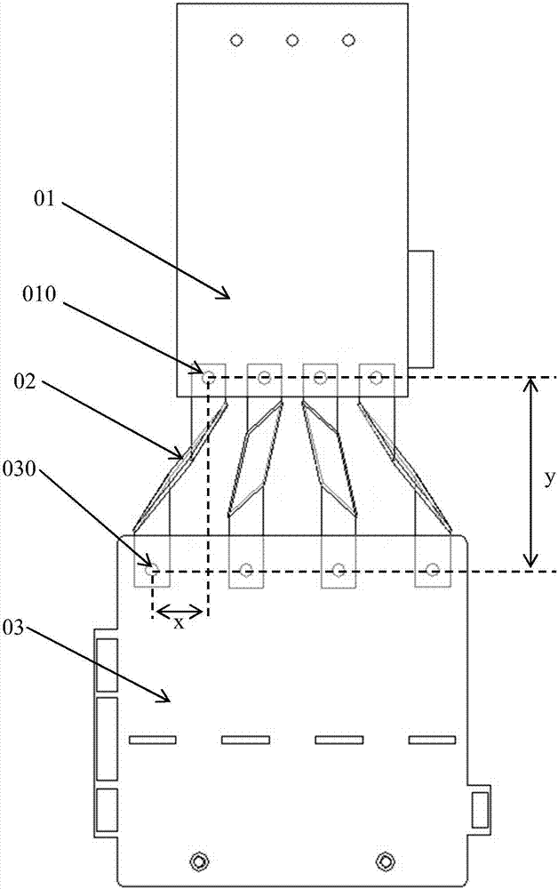
The first type of small current electrical connection uses flexible wires, which are only suitable for small current power distribution links; the second type is larger current electrical connections using copper bar splicing, this method can effectively increase the carrying capacity of the carrier, and the scope of use It can involve the transmission link of high current, but this method requires a large number of connections and transfers, the reliability of the system is deteriorated, and a large amount of manpower is required to participate in assembly and maintenance, and a large amount of fasteners are consumed

Method used


Image

  • Current carrier and design method thereof
  • Current carrier and design method thereof
  • Current carrier and design method thereof

Examples


Embodiment Construction

[0022] The present invention will be further described below in conjunction with the accompanying drawings and specific embodiments.

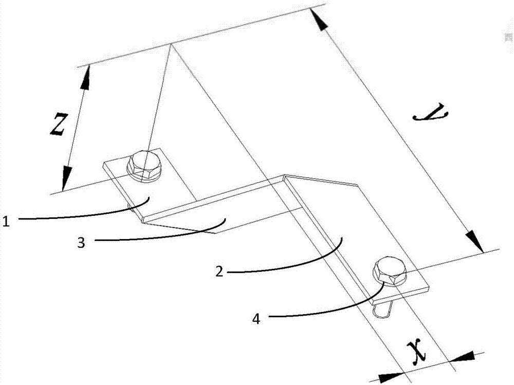
[0023] Such as figure 2 As shown, the current carrier includes a flat metal strip, and the metal strip includes a first bent portion 1, a second bent portion 2 and a middle oblique section 3, the first bent portion 1 and the second bent portion 2 are respectively Located at both ends of the middle oblique section 3, the middle oblique section 3 includes a front and a back, the first bending part 1 bends toward the front of the middle oblique section 3, and the second bending part 2 obliquely toward the middle The back of the bending section 3 is bent, and the first bending part 1 and the second bending part 2 are both provided with through holes 4, and the bolts matching the through holes 4 and the connection points are also drawn in the figure. Other commonly used fixing methods.

[0024] The junction of the first bending part 1 and the mid...


PUM


Abstract

The invention discloses a current carrier and a design method thereof, comprising a flat metal strip, the metal strip comprises a first bent part, a second bent part and a middle oblique bent section, the first bent part and the second bent part The folding parts are respectively located at both ends of the middle oblique section, the middle oblique section includes a front and a back side, the first bending part is bent toward the front of the middle oblique section, and the second bending part is bent toward the middle oblique section The back side is bent, and the first bent part and the second bent part both have through holes. The invention is suitable for the connection of high-current electrical appliances, especially for the electrical connection occasions where there are distance differences in all directions; the integrally formed structure completely solves the hidden danger of reliability caused by splicing carriers of fasteners, and ensures the connection between electrical appliances. The electrical connection performance effectively improves the stability of the power transmission and distribution system; there is no need for a large number of manpower to participate in assembly maintenance and a large amount of fastener consumption, saving costs.

Description

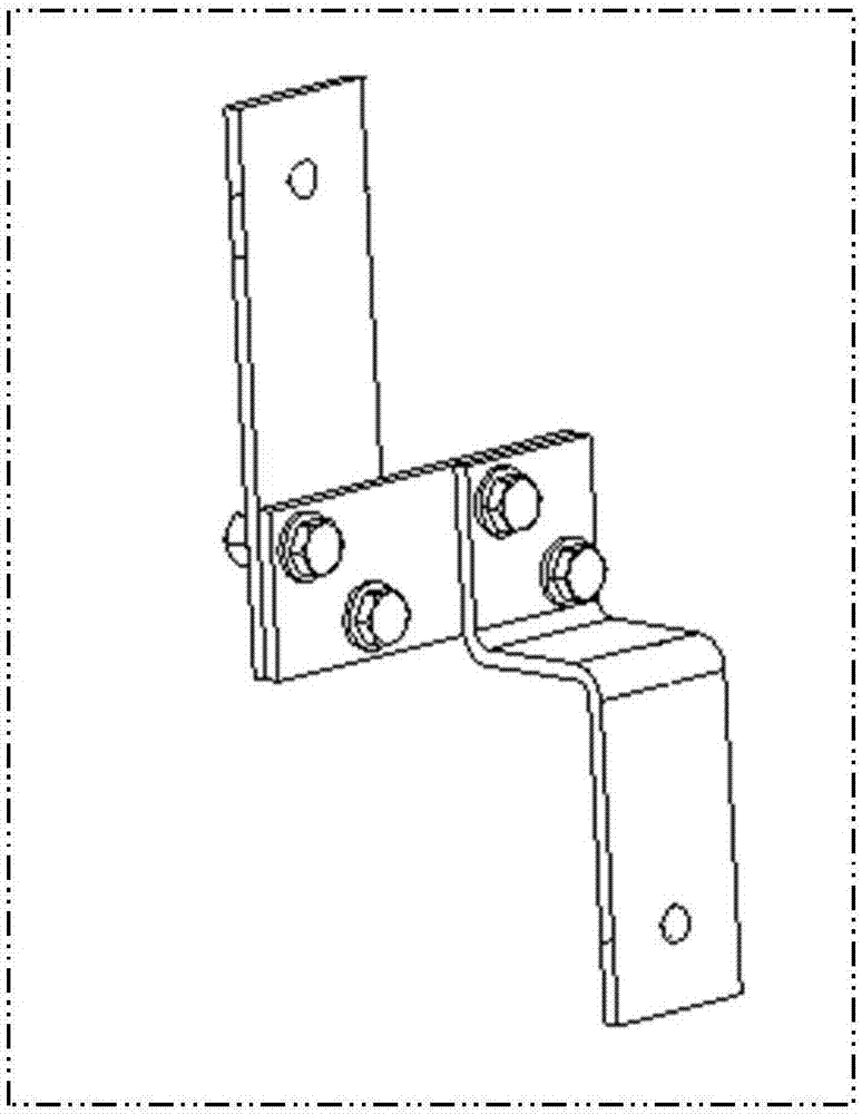
technical field [0001] The invention belongs to the field of electric equipment, and in particular relates to a current carrier used in electric power transmission, power distribution and other links for electrical connection and a design method thereof. Background technique [0002] The power transmission and distribution link in the power system is a complex link with control terminals and power transmission and transformation equipment. There are a large number of switching components, control components and other components inside this link. Electrical appliances are generally connected by current carriers, especially the carriers that carry large currents generally use hard copper bars, such as figure 1 shown. When the location of the electrical appliance is determined, the high reliability of the electrical connection requires the copper bar to have high dimensional accuracy and connection reliability. If the carrier connection is not tight or the surface of the cop...

Claims


Application Information

Patent Timeline
IPC IPC(8): H01B5/02H01B13/00
CPCH01B5/02H01B13/00
Inventor 桑贤臣胡红兵张卫民曹兆敏韩先鹤
Owner NARI TECH CO LTD
Learn More