Eureka AIR delivers breakthrough ideas for toughest innovation challenges, trusted by R&D personnel around the world.

Electrical connector

An electrical connector and electrical connection technology, applied in the direction of connection, fixed connection, circuit, etc., can solve the problems of reducing the volume of the support block, crushing the chip module, and easily breaking the support block.

Active Publication Date: 2017-10-03
DEYI PRECISION ELECTRONIC IND CO LTD PANYU
View PDF6 Cites 13 Cited by
  • Summary
  • Abstract
  • Description
  • Claims
  • Application Information

AI Technical Summary

Problems solved by technology

[0003] However, with the development trend of terminal densification of electrical connectors, the area of ​​the upper surface of the conductive body except the receiving hole must be reduced, so that the upper surface of the conductive body can be used for the support block. The location of the setting is small, which leads to the reduction of the volume of the support block and insufficient strength. When the force applied to the chip module is large, the support block is easy to break, which affects the support of the support block to the chip module. The supporting function of the chip module will cause the chip module to be crushed, and the terminal will be excessively deformed when the terminal is pressed

Method used


Image

  • Electrical connector
  • Electrical connector
  • Electrical connector

Examples


Embodiment Construction

[0041] In order to facilitate a better understanding of the purpose, structure, features, and effects of the present invention, the present invention will now be further described in conjunction with the accompanying drawings and specific embodiments.

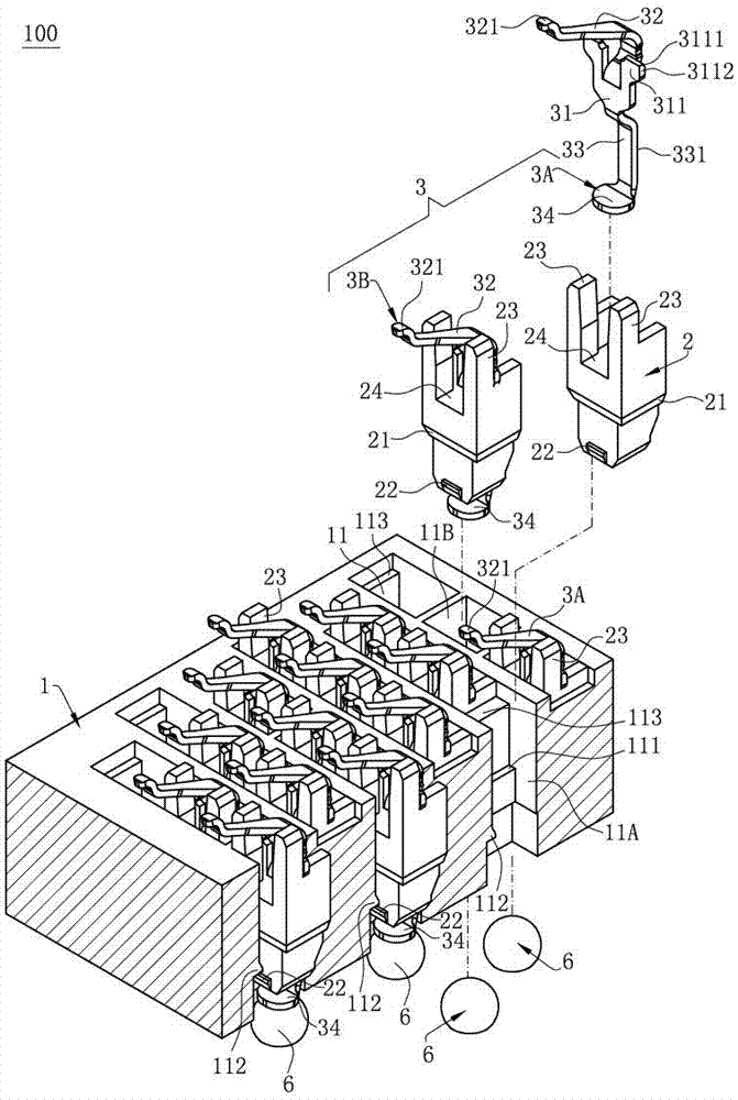
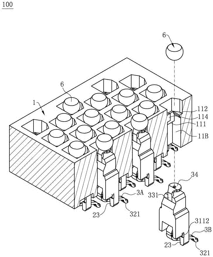
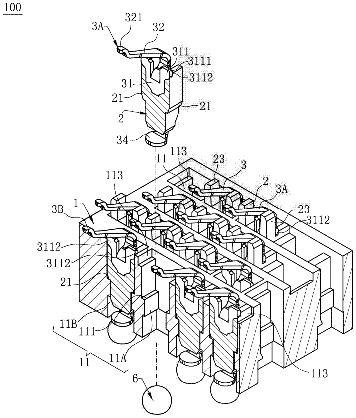
[0042] Such as figure 1 and Figure 7 As shown, the electrical connector 100 of the present invention is used to electrically connect a chip module 4 to a circuit board 5, which includes: a body 1, which is provided with a plurality of receiving holes 11 running through the body 1 up and down; Parts 2 are correspondingly accommodated in a plurality of the receiving holes 11; and a plurality of terminals 3 are respectively accommodated in a plurality of the insulating members 2, including signal terminals 3A for contacting signal pads of the chip module 4 to transmit signal, and the ground terminal 3B for contacting the ground pad of the chip module 4, and the structure of the signal terminal 3A and the ground terminal 3B are t...


PUM


Abstract

The invention discloses an electrical connector. The electrical connector is electrically connected with a chip module, and comprises a body, a plurality of insulating parts and a plurality of terminals, wherein the body is provided with a plurality of accommodating holes passing through the body from top to bottom; inner side faces of the accommodating holes and an upper surface of the body are conductive; the plurality of insulating parts are molded separately from the body, and correspondingly fixed in the accommodating holes respectively; the insulating parts are provided with supporting parts which extend upwards out of the accommodating holes, are higher than the upper surface of the body, and are used for supporting the chip module; the plurality of terminals are correspondingly fixed on the insulating parts respectively; and the terminals are provided with contact parts which are pressed against the chip module. The supporting parts are higher than the upper surface of the body, so that short circuit caused by contact of the chip module with the upper surface of the body can be avoided. The supporting parts extend out of the accommodating holes, so that the arrangement space of the supporting parts can be increased; the strength of the supporting parts is enhanced; the supporting effect for the chip module is improved; the chip module is prevented from being damaged under pressure; and the terminals are prevented from being deformed excessively under pressure.

Description

technical field [0001] The invention relates to an electrical connector, in particular to an electrical connector electrically connecting a chip module to a circuit board. Background technique [0002] The Chinese patent with the patent number CN201120410159.2 discloses a shielded connector for electrically connecting a chip module, which includes a conductive body with a plurality of receiving holes; a plurality of insulators are respectively fixed on In the receiving hole, a plurality of terminals are correspondingly fixed to the insulator, and a plurality of insulating support blocks protrude from the top surface of the conductive body to support the chip module. When the chip module is installed on the shielding connector, the supporting block abuts against the lower surface of the chip module, which can prevent the contact points on the chip module from contacting the conductive body to cause a short circuit. [0003] However, with the development trend of terminal den...

Claims


Application Information

Patent Timeline
IPC IPC(8): H01R12/52H01R12/57H01R13/40H01R33/74
CPCH01R12/523H01R12/57H01R13/40H01R33/74
Inventor 朱德祥王军吴永权
Owner DEYI PRECISION ELECTRONIC IND CO LTD PANYU
Why Eureka
Eureka Blog
Learn More