
Strip-shaped material smashing device

A crushing device and material technology, applied in the direction of grain processing, etc., can solve the problems of being easily wound on the motor shaft or cutter, affecting the service life of the grinder, increasing the production cost of the enterprise, etc., achieving simple structure and improving crushing efficiency , to avoid the effect of stuck

Active Publication Date: 2017-10-10
SUZHOU JINXIANG TITANIUM EQUIP
View PDF4 Cites 0 Cited by
  • Summary
  • Abstract
  • Description
  • Claims
  • Application Information

AI Technical Summary

Problems solved by technology

Because the strip material is relatively long, when the cutter is chopping, the strip material will easily wind up on the motor shaft or the cutter, causing the motor to be stuck, affecting the service life of the pulverizer and increasing the cost of the enterprise. Cost of production

Method used


Image

  • Strip-shaped material smashing device
  • Strip-shaped material smashing device

Examples


Embodiment Construction

[0016] The present invention will now be described in further detail with reference to the drawings and embodiments. These drawings are simplified schematic diagrams, which only illustrate the basic structure of the present invention in a schematic manner, and therefore only show the constitutions related to the present invention.

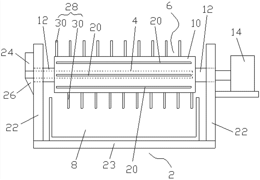
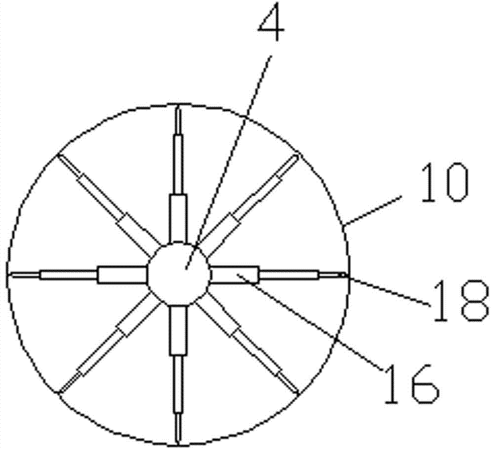
[0017] Such as figure 1 , figure 2 As shown, a strip material crushing device includes a stand 2, a fixed rod 4, a roller 6 installed on the stand 2, and a receiving groove 8 located below the roller 6, the roller 6 includes a roller body 10 , Two support shafts 12 fixed on the two shaft ends of the roller body 10, both support shafts 12 pass through the stand 2, one of the support shafts 12 is connected to a motor 14, the motor 14 is fixed on the stand 2, the motor 14 can drive the roller 6 to rotate. One end of the fixed rod 4 extends into the roller body 10, and the other end passes through another support shaft 12 to be fixed to the stand 2. The ...


PUM


Abstract

The invention relates to a strip-shaped material smashing device. The strip-shaped material smashing device comprises a vertical frame, a fixed rod, a roller mounted on the vertical frame, and a material collection tank below the roller, wherein the roller comprises a roller body and two fulcrum shafts fixed to the two shaft ends of the roller body; the two fulcrum shafts penetrate through the vertical frame; one fulcrum shaft is connected with a motor; one end of the fixed rod stretches into the roller body; the other end of the fixed rod penetrates through the other fulcrum shaft to be fixed to the vertical frame; a plurality of cylinders are fixed to the fixed rod at intervals in the circumferential direction; the cylinders are connected with cutters; a plurality of through holes are formed in the roller body at intervals in the circumferential direction; and the cutters and the through holes are oppositely arranged. According to the strip-shaped material smashing device, a plurality of blocking parts are axially fixed to the roller body, strip-shaped materials are neatly wound and stacked on the roller body, a plurality of strip-shaped materials can be wound on the roller body and are smashed at a time, the strip-shaped materials are smashed into quite small sections, further smashing of follow-up procedures is facilitated, and jamming of follow-up processing equipment is avoided.

Description

Technical field [0001] The invention relates to the field of mechanical processing equipment, in particular to a strip material crushing device. Background technique [0002] The working principle of the existing pulverizer is to first put a plurality of strip-shaped materials from a feeding hopper into a barrel, and the cutter in the barrel is driven to rotate by a motor shaft to cut the strip-shaped material into small sections or granular shapes. Because the strip material is relatively long, when the cutting knife is in the shredding process, the strip material will be easily wound on the motor shaft or the cutting knife, causing the motor to be stuck, affecting the service life of the crusher, and increasing the company’s Cost of production. Summary of the invention [0003] The invention overcomes the deficiencies of the prior art and provides a strip material crushing device with a simple structure. [0004] In order to achieve the above objective, the technical solution ad...

Claims


Application Information

Patent Timeline
Patent Type & Authority Applications(China)
IPC IPC(8): B02C18/14B02C18/18B02C18/16
CPCB02C18/14B02C18/16B02C18/18B02C2018/164
Inventor 范祥荣
Owner SUZHOU JINXIANG TITANIUM EQUIP
Features
  • Generate Ideas
  • Intellectual Property
  • Life Sciences
  • Materials
  • Tech Scout
  • Unparalleled Data Quality
  • Higher Quality Content
  • 60% Fewer Hallucinations
Learn More