Positioning and clamping mechanism for machining outer circle of brake

A technology for positioning and clamping and braking, which is applied to metal processing mechanical parts, positioning devices, clamping devices, etc., can solve the problems of excessive braking surface of the brake workpiece and uneven braking gap, and achieve the elimination of gaps, installation and disassembly. handy effect

Active Publication Date: 2017-10-10
FANGSHENG AXLE LIUZHOU
View PDF7 Cites 3 Cited by
  • Summary
  • Abstract
  • Description
  • Claims
  • Application Information

AI Technical Summary

Problems solved by technology

[0002] At present, the positioning tooling for outer circle processing of drum brakes uses a positioning mandrel and the brake base plate of the brake for small gap positioning; during processing, the workpiece is in contact with the processing tool, and due to the existence of a matching gap, the brake base plate will move towards the gap. One side deviation

Method used


Image

  • Positioning and clamping mechanism for machining outer circle of brake
  • Positioning and clamping mechanism for machining outer circle of brake
  • Positioning and clamping mechanism for machining outer circle of brake

Examples


Embodiment 1

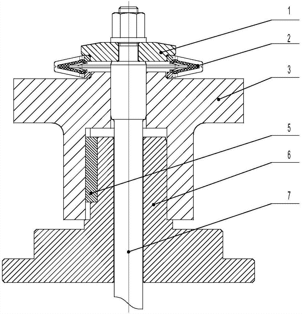
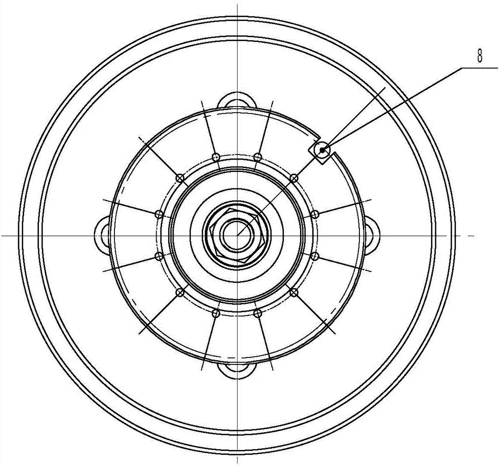
[0034] A positioning and clamping mechanism for brake external machining, see Figure 1 to Figure 2 , including the pressure plate 1, the spring expansion piece 2, the positioning connecting seat 3, the base 6, the tie rod 7, the base 6 is connected with the machine tool, the lower end of the positioning connecting seat 3 is sleeved on the upper end of the base 6, and is connected to the base through the key 5. The seat 6 is fixedly connected; the upper end face of the positioning connection seat 3 is connected with the workpiece 4, and the upper end face of the positioning connection seat 3 is provided with a positioning step II; the pressure plate 1 is located above the positioning connection seat 3, and the bottom of the pressure plate 1 is provided with There is a positioning step I, and the spring expansion piece 2 is sleeved between the positioning step I and the positioning step II. One end of the tie rod 7 is fixed on the pressure plate 1 by a fastener - a nut, and the...

Embodiment 2

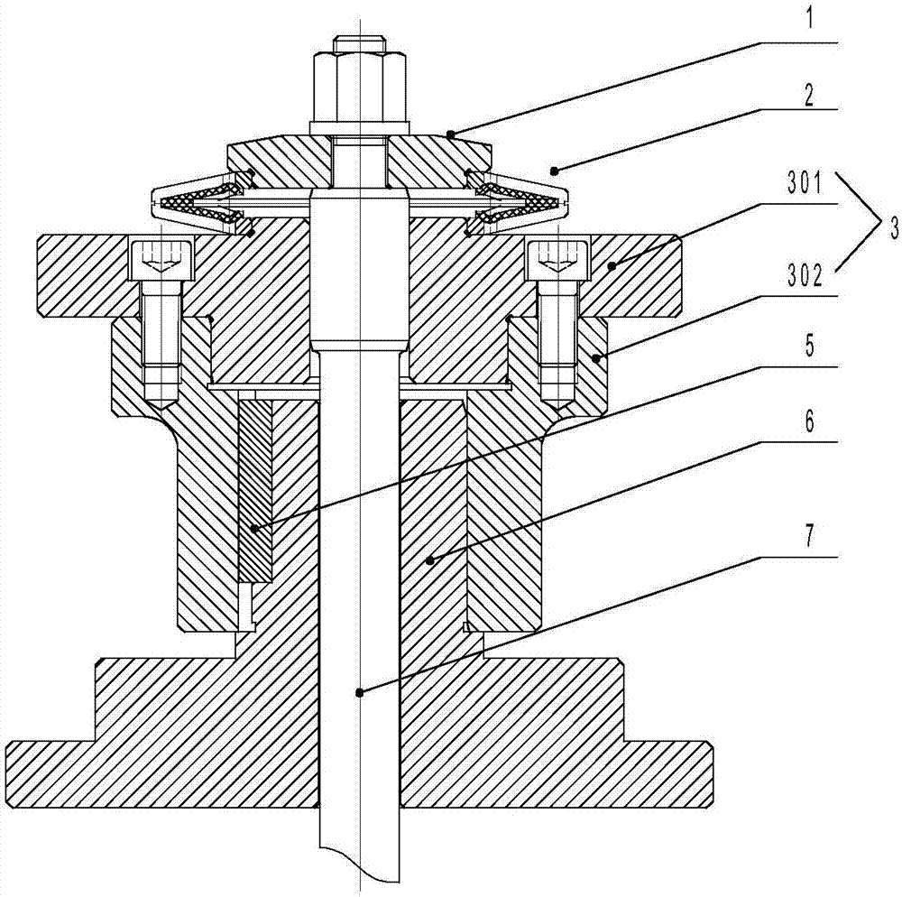
[0036] A positioning and clamping mechanism for brake external machining, see Figure 3 to Figure 4 , including the pressure plate 1, the spring expansion piece 2, the positioning connection seat 3, the base 6, the pull rod 7, the base 6 is connected with the machine tool, the positioning connection seat 3 includes a positioning seat 301, a connecting base 302, and the upper end of the positioning seat 301 The end face is connected with the workpiece 4, and the upper end face of the positioning seat 301 is also provided with a positioning step II. The positioning seat 301 and the connecting base 302 are connected together by fastener bolts; the connecting base 302 is sleeved on the base 6, and is fixedly connected with the base 6 through the key 5; the pressure plate 1 is located above the positioning seat 301, the bottom of the pressure plate 1 is provided with a positioning step I, and the spring expansion piece 2 is sleeved on the positioning Between step I and positioning ...


PUM


Abstract

The invention discloses a positioning and clamping mechanism for machining the outer circle of a brake, and relates to a positioning and clamping mechanism for outer circle machining. The positioning and clamping mechanism comprises a pedestal, a pull rod, a pressing plate, a spring tensioning sheet and a positioning connection base. The pedestal is connected with a machine tool. The lower end of the positioning connection base is arranged at the upper end of the pedestal in a sleeving mode and is further fixedly connected with the pedestal through a key. The upper end face of the positioning connection base is connected with a workpiece. The pressing plate is located above the positioning connection base, and the spring tensioning sheet is installed between the pressing plate and the positioning connection base. One end of the pull rod is fixed to the pressing plate through a fastener, and the other end of the pull rod sequentially penetrates through an inner hole of the pressing plate, an inner hole of the spring tensioning sheet, an inner hole of the positioning connection base and an inner hole of the pedestal and stretches out of the lower side of the pedestal. The outer circle of the pull rod is in sliding fit with the inner hole in the upper end of the positioning connection base. By means of the positioning and clamping mechanism, the gap between a positioning tool and a brake bottom plate can be removed, the positioning and clamping mechanism has the characteristics of being convenient to mount and dismount, low in maintenance cost, reliable in structure and capable of improving machining accuracy, and application and popularization are made easy.

Description

technical field [0001] The invention relates to a positioning and clamping mechanism for outer circle machining, in particular to a positioning and clamping mechanism for outer circle machining of a brake. Background technique [0002] At present, the outer circle machining and positioning tooling of drum brakes all use a positioning mandrel and the brake base plate of the brake for small clearance positioning; during processing, the workpiece is in contact with the machining tool, and due to the existence of a matching gap, the brake base plate will move toward the gap. The deviation of one side will often cause the braking surface of the machined brake workpiece to be out of tolerance. When the tolerance of the positioning hole of the brake base plate deviates upward, and the wear of the positioning tooling deviates downward, this out of tolerance is particularly obvious. When assembling the brake drum , often resulting in uneven braking clearance on both sides. SUMMARY ...

Claims


Application Information

Patent Timeline
IPC IPC(8): B23Q3/00
CPCB23Q3/00B23Q2703/10
Inventor 吴军万李利民荣立帅熊伟张武冠曾勇彭钦飙张智衡
Owner FANGSHENG AXLE LIUZHOU
Why Eureka
Try Eureka