A compact vacuum pump

A vacuum pump, compact technology, applied in the direction of pumps, piston pumps, pump components, etc., can solve the problems of drive circuit board, drive controller damage, unable to detect the air pressure of the pumped container, very troublesome to use, etc., to achieve strong adaptability , Simple repair and maintenance, convenient installation and disassembly

Active Publication Date: 2019-03-22
金华市威科工贸有限公司
View PDF9 Cites 0 Cited by
  • Summary
  • Abstract
  • Description
  • Claims
  • Application Information

AI Technical Summary

Problems solved by technology

Most of the existing vacuum pumps cannot detect the air pressure in the pumped container, and it is difficult for the staff to directly understand the actual air pressure in the pumped container, which is very inconvenient to use
In order to be able to monitor the air pressure in the pumped container in real time, a connecting pipe is often installed on the vacuum pump in the prior art. One end of the connecting pipe is connected to the vacuum pump, and the other end is connected to the pumped container. Although such a setting can monitor the air pressure in the pumped container in real time, because the pressure gauge is installed externally, the pressure gauge is easy to be bumped during use, and it is easy to cause damage to the pressure gauge. The possibility of the small pressure gauge being damaged, it is very troublesome to use the pressure gauge that needs to be temporarily installed every time it is used
In order to improve the performance of the vacuum pump, the ordinary AC motor on the vacuum pump is generally replaced with a DC brushless motor. However, the DC brushless motor needs a special drive circuit board or a drive controller for control. The drive circuit board and drive controller are directly installed on the The casing on the vacuum pump is easy to cause damage to the drive circuit board and drive controller due to collision, resulting in damage to the vacuum pump

Method used


Image

  • A compact vacuum pump
  • A compact vacuum pump
  • A compact vacuum pump

Examples


Embodiment 1

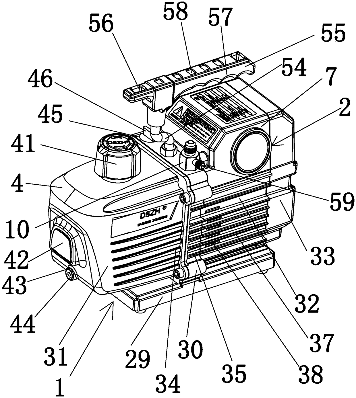
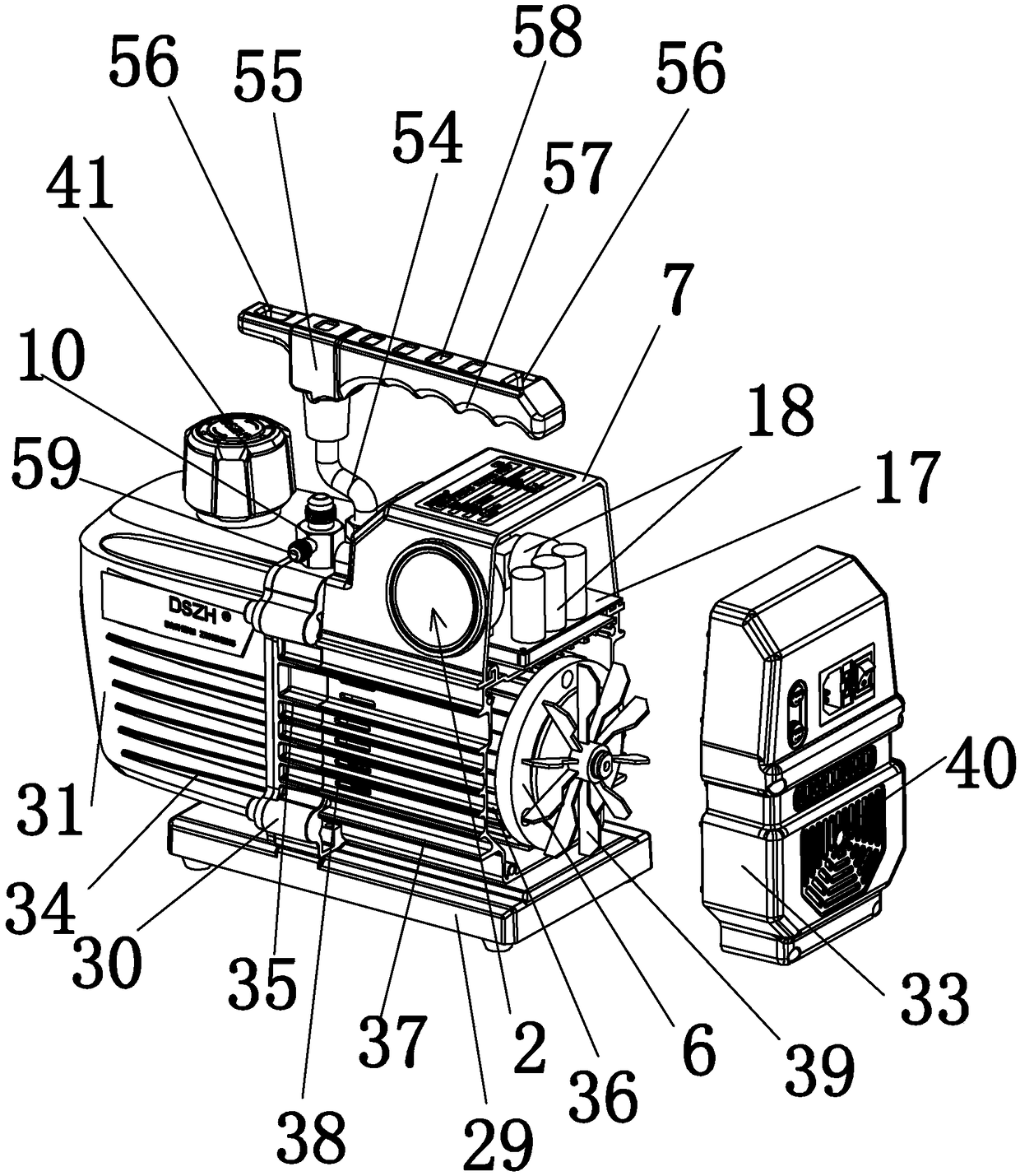
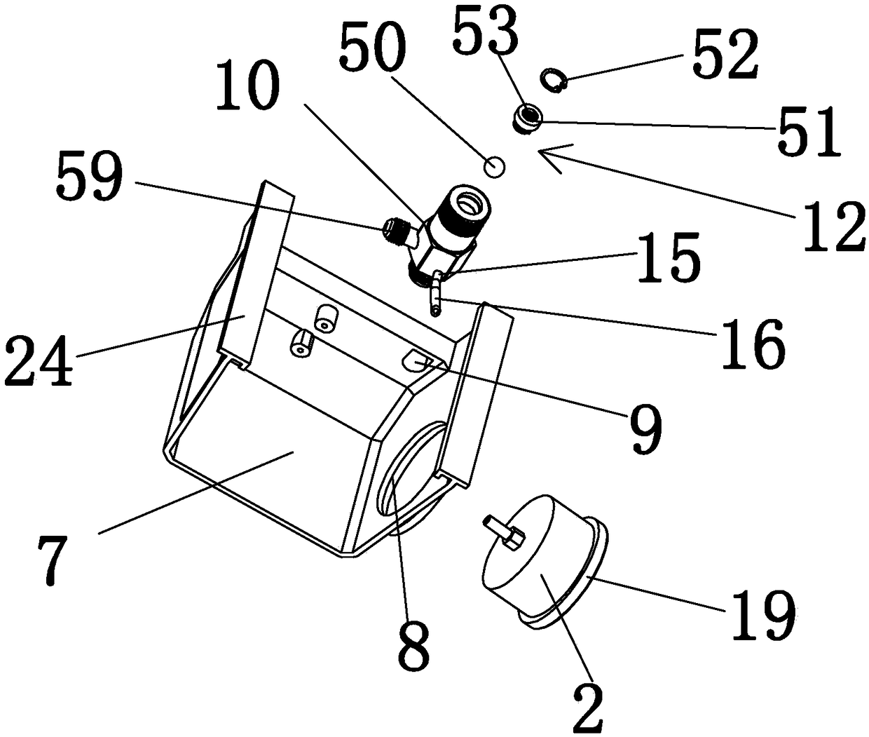
[0030] like Figure 1-6 As shown, a compact vacuum pump includes a vacuum pump main body 1 and an air pressure gauge 2, a protective cover 7 is detachably and fixedly installed on the casing of the vacuum pump main body 1, and a mounting hole 8 and a through hole 9 are opened on the protective cover 7, The air pressure gauge 2 is a digital display pressure gauge. The digital display pressure gauge includes a circuit board 20 and a digital display screen 21 fixedly connected to the circuit board 20. The circuit board 20 is arranged in the protective cover 7, and the digital display screen 21 is embedded and installed. In the hole 8, the measurement port of the digital display pressure gauge is arranged on the circuit board 20, the inner side wall of the protective cover 7 is fixedly connected with a fixing strip 22, and the fixing strip 22 is arranged next to the installation hole 8, and the digital display screen 21 It is fixedly installed on the circuit board 20, and the circ...

Embodiment 2

[0036] like Figure 7-10 As shown, compared with Embodiment 1, the difference between Embodiment 2 is that the air pressure gauge 2 adopts a digital display pressure gauge, which includes a circuit board 20, a digital display screen 21 fixedly connected to the circuit board 20, and the circuit board 20. The board 20 is arranged in the protective cover 7, the digital display screen 21 is embedded in the installation hole 8, the measurement port of the digital pressure gauge is arranged on the circuit board 20, and the inner side wall of the protective cover 7 is fixedly connected with a fixing strip 22. , the fixing bar 22 is arranged beside the installation hole 8 , the digital display screen 21 is fixedly installed on the circuit board 20 , and the circuit board 20 is fixedly installed on the fixing bar 22 by screws.


PUM


Abstract

The invention provides a compact type vacuum pump aiming to overcome the defect that as a pressure gage temporarily additionally installed on a vacuum pump and a drive circuit board used for driving a motor are directly installed on a vacuum pump case, damage is easily caused due to collision in the prior art. The compact type vacuum pump is fixedly provided with a gas-pressure meter which can monitor the gas pressure in a pumped container in real time, a brushless direct current motor is used as a drive motor of the vacuum pump so that the performance of the vacuum pump can be improved, at the same time, a case of the vacuum pump is provided with a protection cover used for protecting the gas-pressure meter and a drive circuit board, damage to the gas-pressure meter and the drive circuit board due to collision in the use process is prevented, the structure is compact, and the vacuum pump is convenient to carry.

Description

technical field [0001] The invention relates to a vacuum pump, in particular to a compact vacuum pump. Background technique [0002] Vacuum pump refers to a device or equipment that uses mechanical, physical, chemical or physical-chemical methods to evacuate the pumped container to obtain a vacuum. vacuum device. Most of the existing vacuum pumps cannot detect the air pressure in the pumped container, and it is difficult for the staff to directly understand the actual air pressure in the pumped container, which is very inconvenient to use. In order to be able to monitor the air pressure value in the pumped container in real time, a connecting pipe is often added to the vacuum pump in the prior art. One end of the connecting pipe is connected to the vacuum pump, and the other end is connected to the pumped container. Although this setting can monitor the air pressure in the pumped container in real time, because the pressure gauge is externally installed, the pressure gauge...

Claims


Application Information

Patent Timeline
Patent Type & Authority Patents(China)
IPC IPC(8): F04B35/04F04B37/14F04B39/12
CPCF04B35/04F04B37/14F04B39/121
Inventor 王德胜王横王纵
Owner 金华市威科工贸有限公司
Why Eureka
Try Eureka