Cylinder

A cylinder block and cylinder body technology, applied in the field of cylinders, can solve the problems of easy failure, increased manufacturing cost, and increased manufacturing man-hours, and achieve the effect of easy manufacturing and easy maintenance

Inactive Publication Date: 2017-10-10
TADANO LTD
View PDF11 Cites 2 Cited by
  • Summary
  • Abstract
  • Description
  • Claims
  • Application Information

AI Technical Summary

Problems solved by technology

Therefore, the structure of the cylinder becomes complicated, and the manufacturing man-hours increase and the man

Method used


Image

  • Cylinder
  • Cylinder
  • Cylinder

Examples


Embodiment Construction

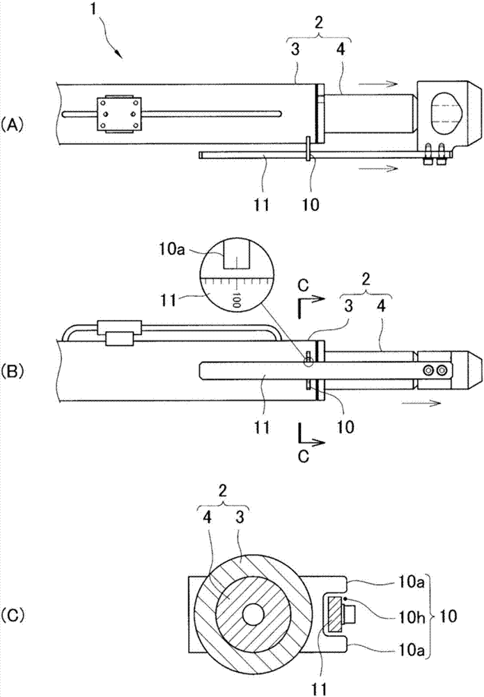
[0025] The cylinder of the present invention is provided with a mechanism for preventing rotation of the rod during expansion and contraction, and is characterized in that the structure of the cylinder can be simplified even if the mechanism is provided.

[0026] The use of the cylinder of the present invention is not particularly limited, and it can be used in a device that needs to prevent the relative rotation of the rod relative to the cylinder when the cylinder expands and contracts, and the like. For example, as the application of the cylinder of the present invention, a cylinder used for detaching and attaching a counterweight of a crane, etc. can be mentioned.

[0027] The working fluid of the cylinder of the present invention is also not particularly limited, and examples of the working fluid include working oil, air, and the like.

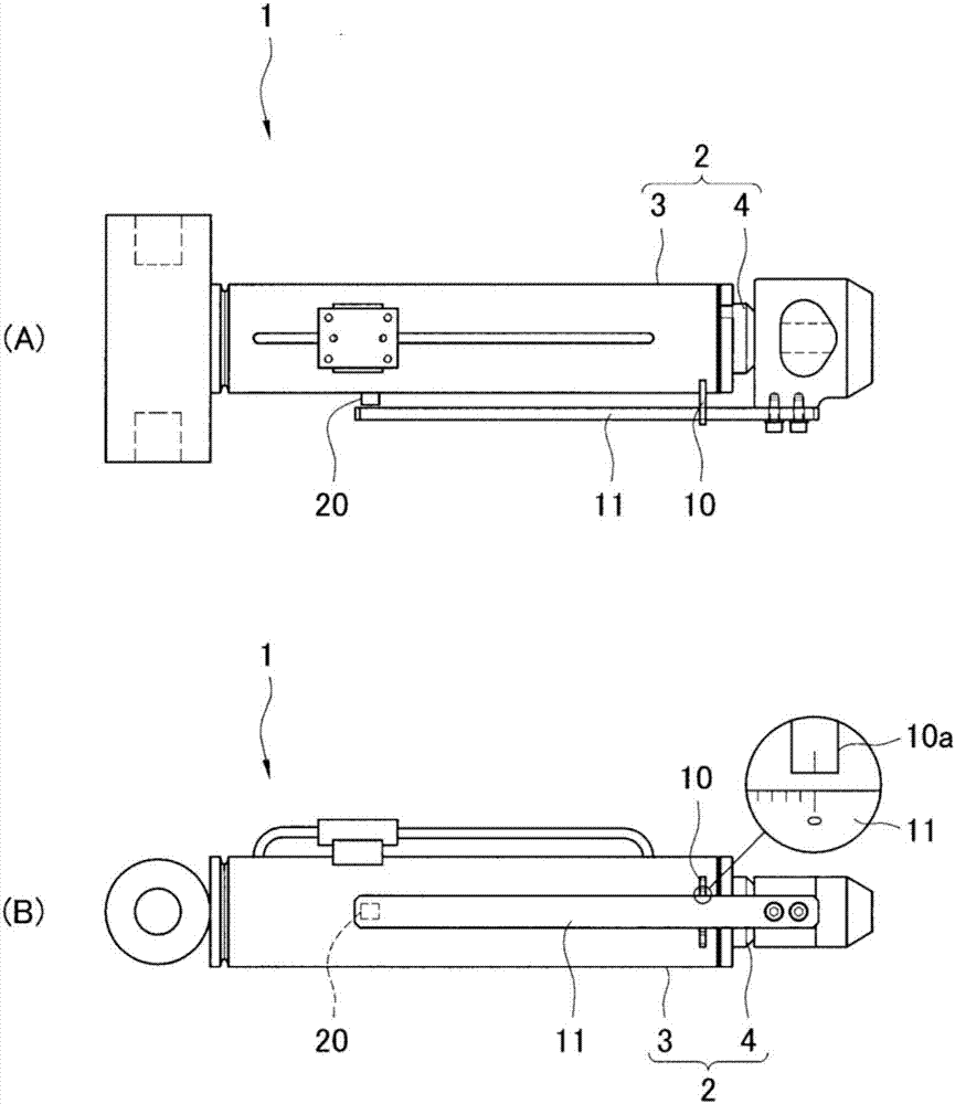
[0028] (Cylinder 1 of this embodiment)

[0029] Such as figure 1 As shown, the cylinder 1 of the present embodiment is provided with ...


PUM


Abstract

The problem addressed by the present invention is to provide a cylinder 2 having a simple structure, with which it is possible to prevent rotation of a rod. The present invention is provided with: a cylinder body 3; a cylinder main part 2 having a rod 4 provided so as to be retractable from the cylinder body 3; a moving member 11 connected to the rod 3, the moving member 11 being provided along a side surface of the cylinder body 2; and a guide member 10 provided on the side surface of the cylinder body 3, the guide member 10 guiding the movement of the moving member 11, the guide member 10 being provided with a movement limiting part 10a for limiting the movement of the moving member 11 in the circumferential direction of the cylinder body 3.

Description

technical field [0001] The present invention relates to cylinders. More specifically, it relates to a cylinder used for moving, fixing, and the like of an object. Background technique [0002] The fluid cylinder has a structure in which the rod is withdrawn from the cylinder by supplying or discharging the working fluid, and an appropriate working fluid is used according to the application. For example, if it is a hydraulic cylinder, it is used for the operation of a press, heavy equipment, etc., and if it is an air cylinder, it is used for an actuator that moves each part on a production line. [0003] In the above-mentioned fluid cylinder, both the cylinder body and the rod are fixed to the working or moving object or frame, or the cylinder body is fixed to other components and the tip of the rod is not fixed to other components. [0004] As an example of the former, there can be mentioned a cylinder that lowers the boom of a crane, and in this case, the relative movemen...

Claims


Application Information

Patent Timeline
IPC IPC(8): F15B15/14
CPCB66C23/74B66C23/82F15B15/14F15B15/28F15B15/1423
Inventor 增田雄大
Owner TADANO LTD
Why Eureka
Try Eureka