Patch integration formula-based umbrella antenna structure optimization design method

An umbrella antenna, optimized design technology, applied in the direction of antennas, electrical components, etc., can solve the problems of not being able to adapt to the umbrella antenna, the principle error of the umbrella antenna, and the difficulty of giving a general calculation process for surface deformation.

Active Publication Date: 2017-10-10
XIDIAN UNIV
View PDF4 Cites 6 Cited by
  • Summary
  • Abstract
  • Description
  • Claims
  • Application Information

AI Technical Summary

Problems solved by technology

[0003] Li Xiaoping and Xu Dehong summarized the two mesh forming methods of the mesh deployable antenna in the paper "Analysis of Two Mesh Surface Forming Methods of the Deployable Mesh Antenna" (Electro-Mechanical Engineering, Vol. 26, No. 1, 2010, 38-40) , gives the formula for calculating the root mean square error of the surface of the umbrella antenna; but this formula only considers the principle error of the umbrella antenna, and it is difficult to give a general calculation process for the surface deformation under any working condition
Wang Congsi et al. and Leng Guojun et al. in the papers "Precise Calculation Method of Antenna Surface Error and Electrical Performance Analysis" (Journal of Radio Science, 2006, Vol. The precise calculation method for the surface error of the ground-based circular parabolic antenna" (Journal of Radio Science, Vol. 24, No. 5, 2009, 826-831) proposed a surface error calculation method and an improved method for ground-based circular parabolic antennas, all of which use the superposition of node errors The root mean square value of the antenna surface error is obtained by this method, which cannot be adapted to the umbrella antenna with larger patches
Ding Bo put forward the idea of ​​using area coordinates for error calculation in "Structure Analysis and Optimal Design of Spaceborne Mesh Deployable Antenna" (Master's Thesis of Xidian University in 2016), but this method is based on the ideal reflector antenna , does not take into account the changing characteristics of the umbrella antenna focal length

Method used


Image

  • Patch integration formula-based umbrella antenna structure optimization design method
  • Patch integration formula-based umbrella antenna structure optimization design method
  • Patch integration formula-based umbrella antenna structure optimization design method

Examples


Embodiment Construction

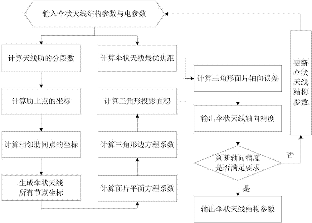
[0078] Attached below figure 1 , the specific embodiment of the present invention is described in further detail:

[0079] The invention provides a method for optimal design of an umbrella antenna structure based on a patch integral formula, comprising the following steps:

[0080] Step 1. Input the structural parameters and electrical parameters of the umbrella antenna provided by the user; the structural parameters include the umbrella antenna aperture, focal length, offset distance, number of ribs and axial precision design requirements; the electrical parameters include the working wavelength;

[0081] Step 2, according to the antenna structure parameters provided by the user, calculate the optimal focal length of the umbrella antenna according to the following formula

[0082]

[0083] Among them, f s Indicates the optimal focal length of the umbrella antenna, the subscript s indicates the umbrella antenna different from the ideal antenna, f indicates the focal lengt...


PUM


Abstract

The present invention discloses a patch integration formula-based umbrella antenna structure optimization design method. The method comprises the following specific steps: inputting the structure parameters and the electrical parameters of an umbrella antenna; calculating the optimal focal length of the umbrella antenna; calculating the segment number of antenna ribs; calculating the coordinates of points on the ribs; calculating the coordinates of points between adjacent ribs; generating all the node coordinates of the umbrella antenna; calculating the coefficient of a patch plane equation; calculating the coefficient of a triangle edge equation; calculating the projection area of the triangle; calculating the axial error of triangle patches; outputting the axial precision of the umbrella antenna; judging whether the axial precision of the umbrella antenna meets the requirement or not; outputting the structure parameters of the umbrella antenna; and updating the structure parameters of the umbrella antenna. According to the technical scheme of the invention, the characteristics of the umbrella antenna spliced by patches are considered. Based on the patch integration formula, the axial precision of the umbrella antenna is analyzed. Therefore, by adopting the method, the mechanical structure design and the electromechanical integrated optimization design of the umbrella antenna are guided.

Description

technical field [0001] The invention belongs to the technical field of radar antennas, in particular to an umbrella-shaped antenna structure optimization design method based on a patch integral formula in the field of radar antennas. Background technique [0002] As a kind of space-borne deployable antenna, the umbrella antenna is a kind of space-borne deployable antenna that has been studied and put into use earlier. Umbrella antennas designed using the characteristics of flexible wire mesh and rigid ribs are being gradually applied to the design of high-gain, light-weight spaceborne antennas. Umbrella antennas use flexible wire mesh to form the antenna reflection surface, which inevitably introduces patch stitching errors, which are principle errors that need to be considered in the concept stage of umbrella antennas. At the same time, the umbrella antenna is affected by external loads such as thermal shock and attitude change in orbit, and the shape of its reflective sur...

Claims


Application Information

Patent Timeline
Patent Type & Authority Applications(China)
IPC IPC(8): H01Q15/14H01Q15/16
CPCH01Q15/141H01Q15/16
Inventor 张树新张顺吉段宝岩黄进张逸群席延
Owner XIDIAN UNIV
Why Eureka
Try Eureka